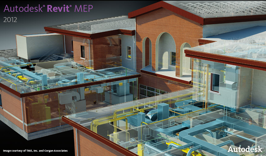
Revit MEP
Monday, December 28, 2009
Wednesday, December 23, 2009
Lochinvar® Develops New Library of Downloadable Revit MEP Models
Lochinvar Corp.
Boiler & Water Heater Families Now Available for Building Information Modeling. Non-parametric parts with MEP connectors.
LEBANON, TN - December 2009 - In response to popular customer demand, Lochinvar® has developed a library of families of its commercial and residential products that are fully configured for placement in Autodesk Revit 2010 building information models. Architects, contractors and designers using the 2010 edition of Revit software, which allows them to design with parametric modeling and drafting elements, can now download the pre-programmed, 3D Lochinvar equipment models for free at
http://www.lochinvar.com/products/documentation.aspx?mode=filetype&filetypeid=22
The library currently includes 26 drawings of key Lochinvar models, such as the ARMOR Commercial Water Heater, KNIGHT XL Commercial Boiler, SHIELD Commercial Water Heater and SYNC Condensing Boiler, as well as the floor-standing KNIGHT Residential Heating Boiler. Additional models are currently in development and will be available for download in the near future.
"After hearing from many of our customers who use Revit on a regular basis, we developed this library in response to their requests for Lochinvar components designed for use with the software," stated Jeff Vallett, executive vice president at Lochinvar. "Now, they can complete their building designs more efficiently and effectively by having quick, easy and free access to pre-programmed drawings of our high-efficiency equipment."
To download the Lochinvar models, visit the "What's Hot" section on the home page at www.Lochinvar.com. They can also be located under the Products tab, by selecting "Product Documentation" and then clicking on the link under "Revit Product Drawings."
For more information about Lochinvar, contact: Lochinvar Corp., 300 Maddox Simpson Parkway, Lebanon, TN 37090; Phone: (615) 889-8900; Fax: (615) 547-1000; www.Lochinvar.com.
Saturday, December 19, 2009
ASHRAE releases free BIM introductory guide
ASHRAE releases free BIM introductory guide:
-- Building Design & Construction, 9/8/2009 8:28:00 AM
A newly released guide from ASHRAE on building information models and building information modeling (BIM) serves as a resource for professionals considering BIM tools and applications for their businesses.
According to "An Introduction to Building Information Modeling," BIM is “a digital representation of the physical and the functional characteristics of a facility.” Unlike 2D or 3D CAD, BIM software utilizes intelligent objects to create models.
The benefits of using BIM applications are numerous, including enhanced interoperability, which will improve integrated building design and integrated project delivery (IPD), according to Dave Conover, a member of the BIM Steering Committee who wrote the guide. Most important, however, is BIM’s ability “to create an accurate model that is useful throughout the entire life of the building, from initial design through occupancy and operation.”
Conover feels that, in addition to the actual benefits of the BIM process, the guide itself offers advantages in that it gives those unfamiliar with BIM “a fast and high level introduction.” He went on to explain that even those already familiar with BIM could benefit from downloading the guide: “It provides some broad level insight into how BIM will affect the building industry in general.”
In addition to BIM’s advantages and tips for getting started with the application, the guide also includes a list of helpful software so that engineers might choose the best program for their company.
An Introduction to Building Information Modeling is available as a free download on ASHRAE’s Web site at www.ashrae.org/publications .
ASHRAE, founded in 1894, is an international organization of some 50,000 persons. ASHRAE fulfills its mission of advancing heating, ventilation, air conditioning and refrigeration to serve humanity and promote a sustainable world through research, standards writing, publishing and continuing education.
Friday, December 18, 2009
Implementing Autodesk® Revit® MEP: A to Z
Implementing Autodesk® Revit® MEP: A to Z
Event Year: Autodesk University 2009
Class ID: MP322-1
Primary Speaker: Todd Shackelford
Class Information
Class Type: 90-Minute Class
Expertise: Intermediate
Industry: Building
Primary Track: MEP Design and Engineering
Primary Software: Revit MEP
Class Audience
CAD managers, IT managers, and engineering professionals
Class Description
This class will outline a framework for transitioning to Revit MEP. From setting expectations and defining goals for Revit, building information modeling (BIM) and integrated project delivery (IPD) to plotting the construction documents, we will walk through the checklist of elements required to help Revit really work in your office. Along the way, this class will demonstrate how to defuse the landmines of a Revit implementation, and some clever Revit tricks will be exposed to smooth the transition.
Key Learning
- Understanding the role of Revit MEP in BIM and IPD
- Creating a Revit MEP template for success
- Creating MEP Families that work for you
- Revit MEP transition tips
- What not to do
Wednesday, December 16, 2009
Don't Go Half Way Using Revit MEP - Creating Systems is a Must
I just got done verifying an process that I've heard mixed issues that result if your workflow process is not correct when using Revit MEP. And it's great news in my opinion.
When you place plumbing fixtures in your Revit Model, it is placed in the Default System.

You can connect multiple plumbing fixtures to each other with pipe, and get all the wonderful flow information - all without adding those fixtures to a specific system that you create. If you select the pipe and look at it's Instant Properties, you can not only see the flow going through those pipes, but you can see that it has a "System TYPE" of Domestic Cold Water and a "System NAME" of Default Domestic Cold Water. Make sure not to confuse the two.

The default View Filter displays System Types of Domestic Cold Water in a blue color. So everything looks good, but there is a limitation of how many plumbing fixtures you can connect to each other that are put on the Default System Name. And that limitation is 50 fixtures.

Below is a thread from Jason Martin at Autodesk explaining the history of this Warning further:
One of the things that is most expensive in the “calculation process” is maintaining the “pressure losses” in sections of a duct or pipe system. To do yhis we divide any connected system into sections at any junction or size change in the system (there are additional reasons for a section to be created, like a resistance change, and I’m sure a few others). For each of the sections we track things like pressure loss, static pressure etc. Maintaining these types of calculations for relatively small sets of elements is relatively inexpensive compared to the time it takes to do things like actually move the things. In systems with thousands of elements, however, these calculations became exponentially more expensive as the element counts increase. We decided at that point that when there are more than a set number of “system assignable-1” elements assigned to a system that we would turn off these types of calculations. After quite a few rounds of testing (as well as some arguing) we decided that a “tolerable” number of elements to turn off these “complex” calculations at was 50. So, now, as soon as the number of elements in a system goes above 50 you’ll get an error message that says something like:
“The default system "Default Supply Air" is now over 50 elements. To improve performance, Revit is no longer calculating the critical path pressure drop and the more complex duct sizing has been disabled. If you want to use these features, you must define logical systems in the model instead of using the default system.”
If you receive this error message it doesn’t have anything to do with things not updating in elevations / sections, and it doesn’t make the application automatically disconnect things. In versions prior to 2009 WU3 (or whichever one it was) it was very true that creating systems improved performance “massively”. Since the introduction of the “50 element” rule, it isn’t as significant as it once was.
For other “performance” things, it really, really, really depends. In 2010 a significant portion of effort was spent on improving the performance of what we referred to as “model manipulation”. This includes things like dragging, connecting, moving, sizing (either with sizing tools or just changing the size), and deleting items like pipe, duct and fittings. As a few others have mentioned here, “model manipulation” in 2010 is significantly faster than it was in previous releases.
If you are moving a connected duct / pipe / fitting - our internal testing has shown that it is actually “slightly” faster to not have systems defined than it is to have systems defined. If you are making new connections between things - our internal testing has shown that it is actually “slightly” faster to have systems defined than it is to not have them defined. If you are changing the flow of elements in the system (like air terminals) - it is “slightly” faster to have systems defined than it is to not have them defined. If you are creating systems - it is significantly faster to create them before things are connected with ducts and pipes.
System assignable elements are things like air terminals, mechanical equipment etc. Things that when you select them you see a create system button (or edit system button) but don’t include things like ducts, fittings, pipes, etc.
Once you create your user defined system, you can move your plumbing fixtures to that system and they are moved out of the default system.


Your piping properties will now take on that System Name as well.

With this, you can create piping annotation tags that can be smart and extract the pipe size and the pipe system. Once I connect a tag to that pipe, it will read, 1" CW. And the tag will automatically update and change if I ever make a change to my design. I don't need to worry about the annotation being incorrect. I like to use these piping annotation tags in my "plot" views for my construction documents.
I also use another piping annotation tag that displays fixture units and flow at certain points of my system in my "modeling" views. That way I can make sure my system is connected, and I'm engineering it properly.
I asked Martin Schmid from Autodesk if you could theoretically put every cold water plumbing fixture in a job in one user defined cold water system, and not have a large performance hit. He says there is a trade-off - and that, even though you can put all of your mechanical fixtures in a user defined system name, the more connections and fittings you have, the longer the calculation time for edits done to the system or its layout. But it's not as bad as when you are using the default system name. Martin tells me that 2010 is faster than 2009 in this process. And you won't notice hardly in smaller jobs.
Another workflow process is that you could break up your systems into CW1 and CW2 and CW3, etc... one for each riser in a particular area. But who wants to have a system name CW4? So you will need to decide if you want to break up your systems, or depending on your project size, computer speed, OS and patience, put all of your fixtures in one user defined system.
Which brings me to the name of the article, Don't Go Half Way. I hear a lot of firms that just want to model certain parts of the building in Revit, and do 2D for the other in AutoCAD. Or they want to just create a 3D model, and not use the flow calculation tools that Revit has. But there are a lot of things going on in the program that if you're not aware of, you run into these limitations such at connecting 50 elements to a default system and you end up creating more headaches than you thought you were going to avoid by taking shortcuts. So go the extra step and create the systems and use them to your advantage. You can save so much more time accepting the full Revit process the way it is supposed to be used, than trying to come up with workarounds and unproven processes of how Revit is not supposed to be used.
Which brings me to the name of the article, Don't Go Half Way. I hear a lot of firms that just want to model certain parts of the building in Revit, and do 2D for the other in AutoCAD. Or they want to just create a 3D model, and not use the flow calculation tools that Revit has. But there are a lot of things going on in the program that if you're not aware of, you run into these limitations such at connecting 50 elements to a default system and you end up creating more headaches than you thought you were going to avoid by taking shortcuts. So go the extra step and create the systems and use them to your advantage. You can save so much more time accepting the full Revit process the way it is supposed to be used, than trying to come up with workarounds and unproven processes of how Revit is not supposed to be used.
Tuesday, December 15, 2009
Real Life Plumbing Design in Autodesk® Revit® MEP
Real Life Plumbing Design in Autodesk® Revit® MEP
Event Year: Autodesk University 2009
Class ID: MP222-1
Primary Speaker: Amelia McCracken
Class Information
Class Type: 90-Minute Class
Expertise: Intermediate
Industry: Building
Primary Track: MEP Design and Engineering
Primary Software: Revit MEP
Other Software: AutoCAD
Class Audience
Plumbing design engineers who have intermediate experience with Revit MEP
Class Description
This presentation will give knowledgeable insight about the advantages of using a 3D software program to not only aid in coordination but to save design drafting time. We will take an in-depth look at how to make plumbing design in Revit MEP work for projects by developing a design guideline. There are numerous features inside the Revit MEP program that can help in designing—the trick is to know what you can and can not utilize. The class will benefit plumbing design engineers who are looking to make Revit MEP work for their projects, whether the design is for high-rise commercial office buildings or low-rise lab buildings. Attendees should have plumbing design background and have a general usage knowledge regarding the Revit MEP software.
Key Learning
- Using Filters to depict classic design standards for piping and equipment
- Pipe types and how to utilize them to improve the time it takes to design
- Schematic 2D plans vs. 3D representation on plans
- What to model, what not to model to match a 2D plan
- 3D Isometrics as plumbing risers
New Content Posted to subscription center for Revit MEP
Autodesk announced that a new US content is now available for Revit MEP customers that are on subscription on the subscription center. The download is called the "US Content Extension for Autodesk Revit MEP 2010"
The US Content Extension for Autodesk® Revit® MEP 2010 software provides new content to help electrical engineers, drafters, and contractors create electrical designs and layouts for projects in the US and elsewhere. Contents include electrical devices for nurse call systems, fire safety, communications, security, and power.
The US Content Extension for Autodesk® Revit® MEP 2010 software provides new content to help electrical engineers, drafters, and contractors create electrical designs and layouts for projects in the US and elsewhere. Contents include electrical devices for nurse call systems, fire safety, communications, security, and power.
Monday, November 23, 2009
Aquity Brand Lighting Products Now in Revit

Models Contain Geometry and Data To Improve All Phases of Construction
The rapid adoption of 3D design tools and building information modeling (BIM) software represent profound challenges and opportunities for the architecture, engineering and design professions.
The potential is that tools like Autodesk Revit® and Bentley MicroStation® will help specifiers create structures that are more sustainable, deliver productivity improvements during design and construction, and provide greater value to owners even faster.
And, in this new era, one of the significant challenges is that specifiers don’t have access to a full and accurate library of 3D models for all of the products that go into a construction project.
Acuity Brands Lighting (ABL) is working with the design community to help improve the promise of BIM by providing 3D models of its lighting products.
Architecture, design, engineering and construction professionals can find a starter set of 3D models of Acuity Brands most popular luminaries on this site. These models will allow designers to seamlessly integrate lighting into project, saving both time and money as they eliminate the guesswork about how the lighting look and interact in the built environment.
This initial set of products is only the beginning. ABL will continue to add more 3D models to our library each month so that designers have access to an ever-growing selection of innovative lighting products.
Taco Revit Familiers

Download them Here
These Revit families are 2009 version.
The families are not the smallest files. They are a bit large. (900k typically). But if you don't have a lot of them, you could make due.
The Taco families are parametric, and there are hundreds of files, one for each pump and they contain all of the data associated with the pump.
There is a Type Catalog TXT file for each Taco family. Make sure that file is in the same location as the family itself.
You can download an entire pump family as a zip file, but then each pump is in another zip file, so you need to unzip each pump, and like I said, there are hundreds of them. Otherwise you can download them on the fly as you need them from Autodesk's Seek site.

Tuesday, November 10, 2009
You don't need Navisworks to create Navisworks NWC files from your AutoCAD or Revit models.
The distributable NWC file exporter program enables project teams using Autodesk Naviswork software to generate whole-project models for simulation and analysis. Project team members can generate the optimized NWC file directly from their design applications. This capability is provided without necessitating a licensed seat of Autodesk Navisworks 2010 software on the same machine. The NWC exporter works with a range of products, including the AutoCAD-based and Revit-based Autodesk products, as well as Autodesk 3ds Max, Bentley MicroStation, and Graphisoft ArchiCAD software. The NWC file format supports transfer of both object geometry and associated metadata from the design applications into Autodesk Navisworks 2010 software.
Click here to download the exporter program
Using NWC File Exporter Pack
The NWC file exporter pack enables project team members generate the optimized NWC files directly from their design applications.
The NWC file enables transfer of both object geometry and associated metadata (such as object properties and materials) from the design applications into Autodesk Navisworks 2010.
The NWC exporter pack works with a range of products including AutoCAD-based applications, Revit-based applications, 3DS MAX and Viz, Microstation, and ArchiCAD.
You can distribute link to a download page for the NWC exporter pack to any project team member.
To export an NWC file from an AutoCAD-based application
- To export an NWC file, type NWCOUT at the command line in the design application.
- Press Return.
- In the Save As dialog box, enter the name for the file, and browse to the desired storage location.
- Click OK to export the file, or Cancel to return to the application without exporting it.
To export an NWC file from a Revit-based application
- In the design application, click Tools ➤ External Tools ➤ Navisworks 2010.
NOTE This option is not available in Demo/Viewer mode. If you are not in demo mode, but do not have access to the Navisworks menu, check if editing view is set to normal, and the modify tool is selected (Edit ➤ Modify). - In the Export Scene As dialog box, enter the name for the file, and browse to the desired storage location.
- Click Save to export the file, or Cancel to return to the application without exporting it.
To export an NWC file from 3DS MAX or Viz
- Click File ➤ Export.
- In the Select File to Export dialog box, select Navisworks 7 Cache (*.NWC) in the Save as Type field.
- Enter the name for the file, and browse to the desired storage location.
- Click Save to export the file, or Cancel to return to the application without exporting it.
Autodesk Brings Together Digital Prototyping and Building Information Modeling
PHOENIX--(BUSINESS WIRE)--Greenbuild Expo 2009--Autodesk, Inc. (NASDAQ: ADSK), a world leader in 2D and 3D design, engineering and entertainment software, announced that building product manufacturers including Reilly Windows & Doors (Reilly) and Mestek, Inc., are successfully using the Autodesk solution for Digital Prototyping to collaborate with the building information modeling (BIM) process and architecture, engineering and construction (AEC) firms.
By providing “BIM-ready” product models that can be directly incorporated into the building design and construction process, product manufacturers help AEC firms make better design decisions around constructability, fit, aesthetics, performance and cost, while increasing their own ability to win new business.
With the growing adoption of BIM in the building industry, AEC firms are increasingly requiring 3D, BIM-ready models from manufacturers as part of the acceptance criteria. Autodesk Inventor software gives building product manufacturers the ability to create digital prototypes of their products and then publish simplified 3D representations with intelligent connectors and product information as BIM objects. These 3D representations can be consumed by the Autodesk Revit suite of products, which are purpose-built BIM applications designed for architects, engineers, and construction professionals. BIM-ready models can also carry important information about a product’s green characteristics, providing early insight into potential LEED certification.
Digital Prototyping as a Competitive Advantage
Reilly designs, fabricates and installs custom windows and doors that exceed the expectations of even the most exacting clients. To create elegant, high-quality products, Reilly relies on a Digital Prototyping workflow based on Autodesk Inventor software to design, visualize and simulate its products digitally and to deliver models of its products to architects who use Autodesk Revit Architecture software.
“Delivering 3D models to architects is a huge value, particularly because most architects can’t spend time creating realistic models of windows and doors,” said Michael John Iwanyczko, director of marketing at Reilly. “We’re offering them highly detailed 3D models that they can incorporate into their architectural designs — it’s another level of service that sets us apart.”
Mestek, Inc., is a family of more than 30 specialty manufacturers providing heating, ventilating and air conditioning (HVAC) products. For more than 40 years, the company has focused on creating a superior indoor environment for building occupants through its offerings. The company recently started using digital prototypes created in Inventor software to develop BIM objects and currently has a published library of more than 300 objects that can be downloaded directly into Revit models.
“The ability to reuse our digital prototypes and repurpose that data to create BIM objects is very important for us, especially since our products tend to be complex and highly configured,” said Mike Kaler, general manager of Mestex, a Dallas-based subsidiary of Mestek. “Sharing these BIM objects with the architects and engineers provides tremendous time savings since we don’t have to create the content from scratch again.”
“Autodesk’s established presence in both the AEC and manufacturing markets is enabling more effective communication and collaboration between disciplines,” said Robert “Buzz” Kross, senior vice president, Manufacturing Industry Group at Autodesk. “Using Inventor software-based solutions allow building product manufacturers to go beyond 3D to Digital Prototyping, and it allows our AEC customers to leverage digital prototypes in their Revit-based BIM workflows.”
Monday, November 02, 2009
AUTODESK REVIT MEP 2010 SUBSCRIPTION RELEASE PACK
User Interface Enhancements
Autodesk® Revit® MEP 2010 software includes enhancements to the user interface, as described in the following topics.
Temporary Dimensions in Layout Mode
When editing duct and piping systems in Generate Layout mode, temporary length and angle dimensions display to assist placement.
DWG Export
When you export a file, you can specify whether to export colors as Index Color or as True Color. See Colors in the User Guide for more information.
Text Formatting Shortcuts
When editing text in a text note, you can format selected text by pressing Ctrl+B for bold, Ctrl+I for italic, or Ctrl+U for underline. See Adding Text Notes and Editing the Text Note in the User Guide for more information.
Split Walls with Defined Space Between Them
The Split with Gap tool allows walls to be split leaving a specified gap between them. See Splitting Elements in the User Guide for more information.
Keyboard Shortcuts
In this release, Revit MEP provides a new interface for managing keyboard shortcuts for Revit tools. With this interface, you can
Several areas of improvements were made in the Subscription Release Pack for Autodesk Revit MEP 2010, including areas such as linked files.
Documentation
For this release, the following enhancements have been made to the Help documentation:
Autodesk® Revit® MEP 2010 software includes enhancements to the user interface, as described in the following topics.
Temporary Dimensions in Layout Mode
When editing duct and piping systems in Generate Layout mode, temporary length and angle dimensions display to assist placement.
DWG Export
When you export a file, you can specify whether to export colors as Index Color or as True Color. See Colors in the User Guide for more information.
Text Formatting Shortcuts
When editing text in a text note, you can format selected text by pressing Ctrl+B for bold, Ctrl+I for italic, or Ctrl+U for underline. See Adding Text Notes and Editing the Text Note in the User Guide for more information.
Split Walls with Defined Space Between Them
The Split with Gap tool allows walls to be split leaving a specified gap between them. See Splitting Elements in the User Guide for more information.
Keyboard Shortcuts
In this release, Revit MEP provides a new interface for managing keyboard shortcuts for Revit tools. With this interface, you can
- Add keyboard shortcuts and assign multiple shortcuts for each Revit tool.
- Remove keyboard shortcuts.
- Import keyboard shortcuts from another user. Also use this function to migrate shortcuts from a previous release.
- Export keyboard shortcuts to share them with other users, or to use the resulting file in a spreadsheet program, where you can sort, organize, and print a list of shortcuts for quick reference.
See Keyboard Shortcuts in the User Guide for more information.
Find and Replace Text in Text Notes
The Find/Replace tool provides a way to find and replace text in text notes in Revit MEP projects. This tool also searches the text in detail groups. You can use this tool to replace placeholder text on several sheets at once. See Finding and Replacing Text Notes in the User Guide for more information.
Convert Line Types
Sometimes the line type in your Revit MEP model is not the type you want to work with. The Convert Lines tool converts existing model lines, detail lines and symbolic lines into the preferred line type. See Converting Line Types in the User Guide for more information.
Several areas of improvements were made in the Subscription Release Pack for Autodesk Revit MEP 2010, including areas such as linked files.
Documentation
For this release, the following enhancements have been made to the Help documentation:
- Walls: This documentation has been revised to improve its organization and provide more conceptual and procedural information.
- Curtain Elements: This documentation has been revised to improve organization and workflow.
- Multi-Discipline Coordination: This section has been greatly enhanced to provide more conceptual, workflow, and procedural information, as well as best practices and troubleshooting about use of the Copy/Monitor and Coordination Review tools.
- Troubleshooting View and Visibility Issues: This new section discusses best practices and suggested solutions for problems with display, view, and visibility.
Autodesk Revit Model Review
From Subscription Only...
Automate the process of reviewing and auditing building information modeling (BIM) projects in Autodesk® Revit® Architecture 2010, Autodesk® Revit® MEP 2010, or Autodesk® Revit® Structure 2010 software with the Autodesk® Revit® Model Review plug-in:
Automate the process of reviewing and auditing building information modeling (BIM) projects in Autodesk® Revit® Architecture 2010, Autodesk® Revit® MEP 2010, or Autodesk® Revit® Structure 2010 software with the Autodesk® Revit® Model Review plug-in:
- Check the accuracy and consistency of a model against standards set by your firm, your clients, or industry best practices.
- Correct inconsistencies with a single click or with instructions provided when manual fixes are required.
Wednesday, October 14, 2009
Wednesday, October 07, 2009
Forum Addresses BIM Standards in Texas
http://www.constructech.com/news/articles/article.aspx?article_id=7975&SECTION=1
October 06, 2009
Julian Kang, associate professor and graduate program coordinator, Texas A&M University, www.tamu.edu, College Station, Texas, had a clear reason for wanting to host a BIM (building information modeling) forum in Houston—to talk about everything the industry can do with BIM, specifically in the construction phase of a project.
Three years ago, Kang did a BIM investigation as part of research efforts for the AGC (Associated General Contractors of America), www.agc.org, Arlington, Va., and found general contractors in the Houston area did not clearly understand how much they can accomplish using BIM.
When he met George Pontikes, chairman of the board, AGC Houston Chapter, and president and CEO, Satterfield & Pontikes Construction, www.satpon.com, Houston, Texas, Kang brought up the idea of offering a BIM forum in Houston, and coincidentally Pontikes had a similar idea. With a program committee, Kang and Pontikes began making decisions and promoting the first BIM forum in Houston.
The BIM Forum Houston 2009, http://bim.tamu.edu/, took place Sept. 17, 2009 and had roughly 90 people in attendance. The event focused on BIM issues and trends in the construction phase of a project. With two keynotes, six breakout sessions, two interactive presentations, and a panel discussion, the event was full of best practice stories and emerging technology.
While one keynote—reported by the AGC—focused on the current economic situation, it was the other keynote—from the Texas Facilities Commission—that garnered a lot of attention, according to Kang.
Recently, the FDC (Facilities Design and Construction Division) within the TFC (Texas Facilities Commission), www.tfc.state.tx.us, Austin, Texas, adopted BIM for state design and construction projects, in an effort to standardize the use of BIM in future projects.
Texas is not the first state to develop a set of BIM standards and guidelines for all partners involved in a state project. Earlier this summer, the Division of State Facilities in Wisconsin prepared BIM guidelines and standards, which were implemented on July 1.
Chris Tisdel, director of building information modeling, TFC, presented the keynote at the BIM Forum Houston.
“He is one of the courageous guys in the construction industry who is preaching the benefits of BIM in construction as an owner,” says Kang. “So, if you want to get a project from the State of Texas, you have got to use BIM.”
Tisdel even talked of specific applications that should be used. According to Kang, Tisdel is asking companies working with the State of Texas to use Revit Architecture from Autodesk, www.autodesk.com, San Rafael, Calif. At the forum, contractors learned about the state’s BIM template for project team members and learned how to incorporate BIM into the lifecycle of projects.
Kang says Tisdel presented many benefits of the standards and guidelines including interoperability, reducing redundant work, and sharing information with others on the team.
“He is basically talking from the owners’ perspective. He wishes to have some central repository where he can get all kinds of 3D models—in this case Revit models—of all buildings that was awarded by the State of Texas,” says Kang.
Another hot topic at the forum was the use of COBIE (Construction Operations Building Information Exchange) to continue to use BIM even after the construction is over.
According to the National Institute of Building Sciences’ WBDG (Whole Building Design Guide), www.wbdg.org, Washington, D.C., COBIE simplifies how work is captured and exchanged. The approach is to enter the data as it is created during design, construction, and commissioning. While it is intended to work within the BIM process, the data can also be exchanged using spreadsheets. Many attendees focused on COBIE and how to use the building information model for facilities management.
Kang says overall event and attendee response exceeded his expectations and he is planning to expand the program next year—beyond just Houston.
“I guess what I would like to say is next year’s forum is … going to be a forum for everybody in Texas,” says Kang. “It is a forum for people that want to see more BIM coming to the construction industry.”
LATISTA Field Integrates Autodesk Navisworks BIM in the field
LATISTA Field Integrates Autodesk Navisworks BIM in the field
Autodesk Navisworks BIM models, synchronized through LATISTA, contain information for quality assurance (QA/QC), collaboration, production tracking, and materials tracking on the jobsite and in the construction office.
Reston, VA (PRWEB) October 7, 2009 -- LATISTA Technologies, a leader in construction automation and field management solutions, announced that LATISTA Field automation software has integrated Autodesk Navisworks project design and synchronized BIM modeling capabilities. Autodesk, Inc., is a provider of computer aided drawing (CAD) and building information modeling (BIM) software.
LATISTA Field was developed specifically to be used on the jobsite with portable tablet PCs. Now it includes Autodesk Navisworks BIM capabilities to improve collaboration between the office and the jobsite.Combining LATISTA Field's mobile and web-based solution with comprehensive Navisworks models enables owners, architects, engineers, and construction professionals to update, access, and share information on a single construction model on and off the jobsite. LATISTA Field is leading the way in linking BIM technologies to the LATISTA Enterprise quality and field operations management solution.
To improve efficiency and accuracy, LATISTA integrates information from the Navisworks model and augments in LATISTA Field it with statuses, issues, and actions for automating field operations including quality assurance and control (QA/QC), materials tracking, production tracking, punch list and commissioning.
With a mobile tablet PC in the field, a LATISTA user can key in or scan the item's tag code from RFID or barcode and status the item. Back at the office, the Naviswork model is automatically updated with the latest statuses from the field, generating an instant up-to-date view of the project's progress. Project teams and owners benefit from having a visual representation of the latest information from the field, since shared information leads to less confusion and fewer delays.
"Our software is already proven to reduce a construction project's time and cost," said Chris Ramsey, Executive Vice President of LATISTA, "Adding Autodesk's BIM information into LATISTA and enabling project teams and owners to view LATISTA information in Navisworks only compounds the return on investment for our customers."
Autodesk Navisworks BIM models, synchronized through LATISTA, contain information for quality assurance (QA/QC), collaboration, production tracking, and materials tracking on the jobsite and in the construction office.
Reston, VA (PRWEB) October 7, 2009 -- LATISTA Technologies, a leader in construction automation and field management solutions, announced that LATISTA Field automation software has integrated Autodesk Navisworks project design and synchronized BIM modeling capabilities. Autodesk, Inc., is a provider of computer aided drawing (CAD) and building information modeling (BIM) software.
LATISTA Field was developed specifically to be used on the jobsite with portable tablet PCs. Now it includes Autodesk Navisworks BIM capabilities to improve collaboration between the office and the jobsite.Combining LATISTA Field's mobile and web-based solution with comprehensive Navisworks models enables owners, architects, engineers, and construction professionals to update, access, and share information on a single construction model on and off the jobsite. LATISTA Field is leading the way in linking BIM technologies to the LATISTA Enterprise quality and field operations management solution.
To improve efficiency and accuracy, LATISTA integrates information from the Navisworks model and augments in LATISTA Field it with statuses, issues, and actions for automating field operations including quality assurance and control (QA/QC), materials tracking, production tracking, punch list and commissioning.
Our software is already proven to reduce a construction project's time and cost. Adding Autodesk's BIM information into LATISTA and enabling project teams and owners to view LATISTA information in Navisworks only compounds the return on investment for our customers.
With a mobile tablet PC in the field, a LATISTA user can key in or scan the item's tag code from RFID or barcode and status the item. Back at the office, the Naviswork model is automatically updated with the latest statuses from the field, generating an instant up-to-date view of the project's progress. Project teams and owners benefit from having a visual representation of the latest information from the field, since shared information leads to less confusion and fewer delays.
"Our software is already proven to reduce a construction project's time and cost," said Chris Ramsey, Executive Vice President of LATISTA, "Adding Autodesk's BIM information into LATISTA and enabling project teams and owners to view LATISTA information in Navisworks only compounds the return on investment for our customers."
Friday, October 02, 2009
Free Revit MEP - Victaulic Content
CLICK HERE to access a one-time registration form. Victaulic.com will place a harmless cookie file on your computer to track your registration so you will be able to have direct access to the CAD library in the future.
Victaulic will keep all registration information completely confidential and will never share any information with any third party without consent.
My only complaint so far is that you have to download each component or family separately rather than download the intire library. And the families don't have the schematic symbology for single line piping systems if you decide to display your Revit view in Course or Medium Detail Levels.
New! Autodesk - Revit MEP Victaulic Content
You will need Revit MEP Release 2009 or Higher in order to open the pipe fittings.
Victaulic has worked directly with Autodesk and a certified Autodesk content provider to create grooved piping components for use with this building information modeling (BIM) software. This is the only grooved content available for Revit MEP that is Victaulic certified and approved.

Please note that the Revit content will be posted to the website in phases. Please check back
periodically for further product lines.
Autodesk Revit MEP - Victaulic Content
Please follow the instructions below after registering at the Victaulic CAD files and software website.
http://www.victaulic.com/content/cadandsoftware.htm
Note: The downloadable ZIP files were created using WinZip (http://www.winzip.com/)
To Download:
- Locate and select "Autodesk - Revit MEP" from the list of 3rd Party Software Solutions
- Locate and select the required module
- Select required component ZIP file by clicking on the Download File link
- Select the "Save" option in the "File Download" dialog box
- Choose a location to save the file to in the "Save As" dialog box
To Extract CSV File(s):
- Locate the saved ZIP file and double click it to open it
- Highlight the CSV file(s) and select the "Extract" option (see below)
- Type in the location of the Revit lookup table folder in the "Extract to:" area of the "Extract" dialog box. Example: "C:\Documents and Settings\All Users\Application Data\Autodesk\RME 2009\LookupTables"
- Select the "Extract" button in the "Extract" dialog box
To Extract RFA File:
- Highlight the RFA file and select the "Extract" option
- Choose a location for the RFA file
Note: The RFA file can be extracted to any folder either on a local drive (C:\) or to a server location. Example: "C:\Autodesk Revit Content\Victaulic\IPS" - Select the "Extract" button in the "Extract" dialog box
NVIDIA further refines its graphics cards for Revit, NavisWorks, and BIM
NVIDIA further refines its graphics cards:
NVIDIA further refines its graphics cards
Oct 1 2009 12:17PM
By Jeff Yoders
NVIDIA released its 10th generation of professional graphics cards earlier this year. I was given a test NVIDIA Quadro FX 1800 with the HP Z600 workstation for a test drive earlier this year. Here’s a more detailed look at the Quadro FX 1800, a mid-range professional graphics card that would be a good fit for any architecture or engineering firm looking to upgrade its graphics cards with or without new hardware.The Quadro FX1800 has 756 megabytes of onboard memory, two digital display iutputs, and one DVI output, all in a PCI Express interface. The card does not require a separate power connector from your computer’s power supply. While the Quadro FX1800 is listed as a top mid-level card, it’s really the minimum anyone doing heavy CAD or using even the most basic BIM programs should have. Only NVIDIA itself manufactures the Quadro line, so the company can guarantee quality and performance. (Its GeForce consumer line of cards has much more tolerant production specifications and therefore can be outsourced to other manufacturers around the world.) All Quadro cards are certified to run on Windows, Linux, and Mac OS.
Thanks to its partnerships with software manufacturers such as Autodesk and Adobe, NVIDIA makes sure that every Quadro card passes minimum requirementsbefore shipping. Working with AutoCAD 2010, Revit, and Navisworks Manage 2010, my Quadro FX 1800 was ready to use upon installation with the latest Autodesk drivers and also optimized to take more of the workload off my test machine’s processors. The NVIDA Application Configuration Engine, included with every Quadro card, automatically adjusts graphics settings for optimized application performance from the start, eliminating the need to manually adjust settings for different applications.
I noticed the 50% more graphics memory that the Quadro FX1800 boasts over the last generation of NVIDIA cards for interactive visualization of large assemblies and scenes. (The Quadro FX 1500 was used in the HP xw4600 I tested last year.) One test of performance was done by opening multiple large models created in both Revit and AutoCAD. The graphics card was able to significantly speed up the process of opening and viewing the large files. The test took about twice as long on the older machine.
The NVIDIA Quadro FX 1800, easily removed
from my PC with no tools.One welcome improvement in the card’s interaction with AutoCAD 2010 is higher image quality with AutoCAD Smooth Lines. Any card can render a generic line, but will it produce the smooth, high-quality lines that AutoCAD demands? Usually not. That used to lead to only two choices: sacrifice line quality for the sake of performance, or fall back to software rendering and live with the inevitable drop in frame rate. Professional-class cards like the Quadro FX 1800 integrate a fast hardware engine specifically designed to draw AutoCAD-style smooth lines. The aesthetic lines we drew had the desired level of detail with no drop in frame rate, thanks to the card’s processing power.
The Quadro FX 1800 is an excellent solution for any AEC firm looking to upgrade. The out-of-the-box optimization and GPU acceleration for software partners is a huge timesaver for IT departments, too. More than half of NVIDIA’s engineers are actually software engineers, so years of work actually went into making the Quadro FX 1800 this easy to use.
The Quadro FX 1800 is a mid-level graphics card optimized to perform with today's most popular design programs, including
SolidWorks and AutoCAD.


Thursday, October 01, 2009
Revit MEP 2010 Update 2 Just Released
Update 2 is not a full install; rather it is using service pack technology similar to AutoCAD based products.
http://usa.autodesk.com/adsk/servlet/item?siteID=123112&id=12899931
There are two separate downloads…one for 32bit and one for 64bit. Make sure you download the correct version!
This second service pack contains the changes made from the previous service pack (Update 1 - June 2009).
This service pack can be applied to both the standalone and suite versions of Autodesk Revit MEP 2010.
Improvements made in Update 2 build (20090917_1515):
Autodesk Revit MEP 2010 Enhancements
- Wire length in the Circuit Properties dialog will now display “Not Computed” for the wire length when a panel has not yet been assigned to a circuit.
- The calculation of complex space volumes for heating and cooling loads has been improved.
- Panel and circuit information can now be displayed in a mechanical equipment schedule.
- Improved the ability to swap one type of pipe or duct accessory for another type of pipe or duct accessory.
- When use of the Split tool on a duct segment creates a union, the union is no longer automatically deleted when a new duct is connected to the union.
- Improvement of a duct segment centerline alignment when rotated in an elevation view.
- Windows and doors set as demolished will no longer appear in a gbXml export.
- Improved stability when copying elements from one family to another in the Family Editor.
- When the Create Similar tool is used for a sloped pipe, the slope is now properly maintained for the new pipe.
Autodesk Revit Platform 2010 Enhancements
- Annotation objects no longer disappear when panning a view that spans two monitors.
- Improves stability when switching between Autodesk Revit Architecture 2010 software and Google Earth™ software.
- Improves the modification behavior of hosted sweeps (i.e. gutters) attached to joined roofs.
- Improves stability and performance when modifying walls.
- Improvements to shared nested families.
- Improves stability when modifying masses.
- Improves design option rules adherence for walls in different design options and worksets .
- Family and type information can now be read in Autodesk® 3ds Max® software from an FBX® file exported from a non-English version of Autodesk Revit Architecture 2010.
- Improves stability when adding views to sheets.
- Improves stability when making a design option primary.
- Improves stability of printing views in wireframe mode.
- Shadows will no longer be cropped when a view is printed or exported to a DWF™ file.
- Subscription notifications are now available from InfoCenter.
- Improves stability when reading IFC files.
- Improves stability when opening a project with an inserted TIF image and when importing a TIF image.
- ViewCube® navigation tool and the navigation bar will now display correctly after unlocking the computer.
- Improves stability when removing panels from the ribbon.
- Improves stability when cancelling a move, delete or copy command.
- Improves performance of view renaming and the Workset dialog.
- Mass floor schedules will now update when a level is renamed.
- A form element that has a divided surface applied to it will now be correctly generated after a copy, paste, or move.
- Improves stability when exporting to DWG.
- Dimension and spot elevation values will now display correctly in a dependent view.
Monday, September 21, 2009
Wednesday, September 16, 2009
COMPUTATION AND CRAFT: SARUP TECHNOLOGY LECTURE SERIES - FALL 2009
Below is a link to this year’s schedule for the UWM SARUP Computation and Craft Lecture Series…
UW-Milwaukee School of Architecture & Urban Planning (SARUP)
All lectures occur on Thursdays, 12-1:30 pm, at Eppstein Uhen Architects: 333 East Chicago Street in the Third Ward, Milwaukee, WI 53202.
Lectures are free and open to the public. 1.0 AIA / Continuing Education System Learning Unit awarded for each lecture.
SEPTEMBER 24 :
OCTOBER 8 :
UW-Milwaukee School of Architecture & Urban Planning (SARUP)
All lectures occur on Thursdays, 12-1:30 pm, at Eppstein Uhen Architects: 333 East Chicago Street in the Third Ward, Milwaukee, WI 53202.
Lectures are free and open to the public. 1.0 AIA / Continuing Education System Learning Unit awarded for each lecture.
SEPTEMBER 24 :
Zero Carbon Case Studies -
James Wasley
James Wasley is an Associate Professor at UW-Milwaukee and is the SBSE Principal Investigator for the Carbon Neutral Design (CND) project, a joint effort by the AIA and the Society of Building Science Educators (SBSE) to produce educational and resource materials for carbon neutral design. This presentation will highlight case studies that relate to the CND project.
OCTOBER 8 :
Sustainable Curtainwall Design Case Study -
Chris Stutzki, Ph.D.– Stutzki Engineering
Stutzki Engineering, Inc. (SEI) is a consulting firm offering engineering services for architects and building contractors, in the field of structural glass, lightweight structures and building facades- combining state-of-the-art engineering and applied science with creative industrial design. This presentation will highlight an advanced sustainably-focused envelope design for a law school building in Baltimore, on which Stutzki is working in association with BEHNISCH Architekten and TRANSSOLAR.
OCTOBER 15 :
BIM–The Engineering Perspective -
Jerry Packham, Project Manager and Kyle Hansen, Designer Affiliated Engineers, Inc.
Jerry Packham and Kyle Hansen, of Affiliated Engineers, Inc. (AEI), are integrally involved in the firms use of Building Information Modeling (BIM) based technologies and processes to improve project delivery and project performance. This presentation will highlight AEI’s use of BIM from an engineering perspective and will feature examples from projects AEI has delivered utilizing BIM and other related methodologies.
NOVEMBER 5 :
Integrated Project Delivery: Real World Projects -
Mike Whaley, Director of Preconstruction Services – J.H. Findorff & Sons Inc.
Mike Whaley leads Findorff’s preconstruction services and as a result is intimately familiar with virtual construction, Building Information Modeling (BIM) and Integrated Project Delivery (IPD). This presentation will highlight real-world projects, including the Wisconsin Institutes for Discovery project under construction at the University of Wisconsin, where these techniques and technologies have been utilized and have made a difference.
NOVEMBER 12 :
SC Johnson Project Honor – Pioneering in Value Based Design and Construction
Kevin Bredeson – Director of Virtual Construction – Gilbane Building Company
Tracy Lutterman – Construction Project Manager, Corporate Facilities – SC Johnson Company
Jason Chandler – Project Manager – Epstein
Tracy Lutterman – Construction Project Manager, Corporate Facilities – SC Johnson Company
Jason Chandler – Project Manager – Epstein
Designed by world renowned architect Foster + Partners in association with Epstein, and constructed by Gilbane Building Company, Project Honor utilized a unique, collaborative approach to project delivery, The presentation will focus on the unique design of the facility and the necessary collaboration to be able to incorporate the unique design features. Emphasis will also be placed on the upfront collaboration of the integrated project team, the Building Information Model (BIM) and the use of Lean design and construction principles to maximize efficiencies in every aspect of the work.
NOVEMBER 19 :
Fast, Cheap, Better & more sustainable– Case Study in Integrated Project Delivery
Martin Sell – President – MSA Integrated Project Delivery
MSA Integrated Project Delivery recently completed the five-acre Spirit of Africa Exhibit for the International Crane Foundation in Baraboo, Wisconsin. MSA Integrated Project Delivery acted as the IPD team leader for a team comprised of 11 companies. In this presentation, Martin will discuss how using an IPD approach allowed the team to complete the project meeting all of the owner’s goals – on-time completion, financial performance more than 10% under budget, with levels of quality and sustainability beyond what was originally anticipated.
Tuesday, September 15, 2009
Autodesk Navisworks 2010 Service Pack 1 Now Available
Download Here
http://usa.autodesk.com/adsk/servlet/ps/dl/item?siteID=123112&id=13861499&linkID=10382102
General Updates
This service pack fixes the following defects.
http://usa.autodesk.com/adsk/servlet/ps/dl/item?siteID=123112&id=13861499&linkID=10382102
General Updates
This service pack fixes the following defects.
- Clash Detective. Camera now transitions more smoothly between clash results.
- Object Animation. When adding a keyframe to the end of an animation the object movement now remains consistent.
- Comments window. TheID column in the Comments window is now labeled Comment ID.
- Hyperlinks and Smart Tags. Autodesk Navisworks now remembers Hyperlinks and SmartTags visibility settings between sessions. New Show Hyperlinks and Show SmartTags options have been added to the Options Editor (Interface node).
- Sectioning. The section bar slider now maintains correct settings when user switches between viewpoints.
- Collaboration. When using the collaborate function all window states now remain consistent.
- AutoCAD Interoperability. AutoCAD elements are now correctly displayed on the Properties tab of the Selection Tree window.
Installing Autodesk Navisworks 2010 no longer causes issues with AutoCAD VBA customizations. - Inventor Interoperability. You can now view Inventor 'surface models' in Autodesk Navisworks.
- IFC Interoperability. Improved support for IFC 2X2 files. Missing components and misplaced Geometry issues are now resolved.
- Revit Interoperability.
Structural usage text designated in Revit is now displayed in Autodesk Navisworks.
Window and door openings are now supported when exporting NWC files from Revit.
Revit models modelled in mm now appear the correct size in Autodesk Navisworks. - AutoCAD Visual LISP. Visual LISP feature of AutoCAD 2008 and 2009 now functions correctly after Autodesk Navisworks 2010 is installed.
BIMBoy: First Wisconsin, now Texas mandates BIM for state projects
BIMBoy: First Wisconsin, now Texas mandates BIM for state projects: "
Apparently, even Building Information Modeling is bigger in Texas. The Texas Facilities Commission announced yesterday that it is requiring a BIM m..."
BIM: The Future of Plumbing Design?
By Marvin Titlow
http://michaelbradyinc.com/Articles/bim01.pdf
Building information modeling (BIM) is the process of generating and managing building data that can be used from the planning stage, through construction, and well into all stages of a building’s life-cycle. Typically, it uses three-dimensional, real-time, dynamic building modeling software to increase productivity in building design and construction.
The power of BIM is held within the virtual model and its associated database. One can think of it as being able to create “live design.” For instance, a section marker is placed in plan view, and instantly a section view is created. When a selected pump is put into the plan view, a schedule containing flow and electrical information can be created instantly. Flow and pressure drop data for piping and fittings can be included as well. Such information can be extracted and used for material cost comparisons and also can help calculate points for LEED design projects.
Federal and state government agencies are beginning to require BIM to be used in the design of their facilities to help determine long-term building sustainability and to aid in facility management. These agencies normally request that the contractor perform as-built changes to the building model within a set number of days to maintain the accuracy of the model.
Figure 1 Parameters are used to input information that controls intelligent objects.

Drafting’s Evolution to Building Information Modeling
Since the beginning of building construction, there has been some form of building information management. From papyrus scrolls used during the building of the pyramids to drafting boards used at the dawn of skyscrapers, designs have been managed in a format that can be referred to for concept, construction, and then ownership.
When computer-aided design (CAD) was introduced, it brought a new dimension to creating line drawings. Rather than needing a compass or triangle, one could type a command, and a circle could be drawn in any size and any scale. A line could be given any length or angle. Even with the slow speed of early computers, copying and deleting could happen at a pace only previously imagined. Building layouts could be changed much more quickly than on the drafting board.
However, this speed came at a price. When plans were designed on the drafting board, architects and engineers met before the building design started to coordinate mechanical room sizes, water heater locations, electrical panel locations, etc. All members of the design team focused on completing the project with as few changes as possible.
With CAD, oftentimes all disciplines are finishing their design the day the project is due, which leads to more change orders and sometimes higher building costs due to the extra coordination and assumptions made by the plumbing contractor because of insufficient information. Autodesk, Bentley Systems, and other CAD software companies have been trying to eliminate this problem for years.
While the concept of constructing drawings in 3D has been around for a long time, the process has been very time consuming and labor intensive with just CAD because these systems are normally vector based. This means that when a line or circle is drawn, it uses X, Y, and Z points as bases of measurement. To perform higher functions of calculations, the vector points are exported to a database.
Building information modeling software has developed as the next step in CAD’s progression. BIM software has taken the approach of creating the model within a database. This allows higher functions to be applied through the use of parameters. Parameters can input more information than units of measurement. They can be used to apply text, graphic overlay for rendering, and referencing information from other databases. The entire model has the ability to be parametric. Rather than lines representing a pump, the pump now has become a virtual object with the ability to contain real-world information such as plan location, elevation, weight, volume, horsepower, pressure loss, and much more (see Figure 1).
The ability to contain a wide variety of data types gives the BIM program the ability to perform calculations and display the information in multiple views in real time (see Figure 2). Several different products on the market today are used to create BIM models (see sidebar).
Workflow and Building Information Modeling
With BIM, one of the biggest concepts that must be embraced is that collaboration must begin early in the schematic design to ensure that major trouble areas such as mechanical rooms or ceiling heights have been coordinated. When entering the design development stage, most of the issues should be resolved so a more accurate price and layout can be achieved. When ready to start the contract documents phase, most of the layout should be complete, leaving only documentation and final coordination.
The most efficient way for this concept to work is for all the disciplines to work in BIM. For instance, at Michael Brady Inc., BIM software packages for the architectural, structural, MEP, and civil engineering disciplines have been utilized since 2006. Some architectural firms that have made the move to BIM have started requesting that out-of-house MEP firms reduce their fees if they produce their plans in CAD due to the increased time spent on coordination. (See Figure 3.)
HOW BIM Will Change Plumbing Design
Many architectural and structural engineering firms that have implemented BIM have stopped hiring CAD operators. Instead, they hire architectural interns and engineering graduates because the lower functions of drafting are being handled by the BIM software. Training for new plumbing personnel should be streamlined to help determine if a plumbing draftsperson can develop the concept of how pipe goes together and what fittings are required to make a system work. When designing in BIM, piping systems are installed in a virtual world, not drawing a line or circle that is printed on a piece of paper. The statement “my drawings are diagrammatic only” no longer applies.
Figure 2 The true power of BIM is its ability to display information in multiple views in real time.

When a company decides to commit to BIM, the plumbing designers will be tasked with learning the new software to produce their designs. The company may need to invest in new computer hardware to run the software effectively. The transition will require training to use the software and might require more time to develop content. This endeavor can take six months to a year before plumbing personnel actually become efficient.
The International Code Council is in the process of developing new standards to incorporate BIM in the code review process. This new project is called SmartCodes. This can have a major effect on plumbing design if plumbing designers and engineers are not involved in the development of this process. There have been numerous discussions about how industry societies need to be more involved in the development of plumbing standards. I believe BIM can be a catalyst. Within BIM’s format, plumbing calculations can be produced to help show building sustainability. Plumbing engineered systems then would have more credibility. (If you would like to learn more about SmartCodes, visit www. iccsafe.org/SMARTcodes.)
Advantages of Using BIM in Plumbing Design
Coordination with other disciplines always has been at the top of our list when designing a system. Being able to work in a virtual 3D environment really helps detect conflicts. Most BIM solutions have a means of performing conflict detection and will highlight the areas in question. Since BIM solutions are normally databases, the ability to track items such as mechanical equipment, plumbing fixtures, fixture unit counts, and gas loads is much easier. Creation of the final documentation is quicker. BIM models normally contain parametric objects, and information can be added to adjust the physical attributes of these objects. If any piece of information needs to be scheduled, a parameter can be created to allow the object to share information with a schedule.
The 3D view of the BIM model can be rotated to different directional planes to produce plumbing isometrics (see Figure 4). Since most BIM software creates the model using databases, streamlining construction specifications can be done through third-party software such as e-Specs. Cost estimating for plumbing systems becomes more accurate due to the requirement for a more accurate layout within the BIM model. Most BIM software allows CAD files to be imported and models to be exported to CAD so other groups that are not using BIM can coordinate.
Disadvantages of Using BIM in Plumbing Design
I have stated some very compelling advantages for using BIM, but there are some disadvantages as well. Since the technology is new, the plumbing portions of these BIM programs are underdeveloped. Because models are databases, one would believe that being able to conduct performance analysis such as hydraulic calculations live in the model would be a strong point of the software. However, as of now this feature is still in development. While isometrics can be produced in Revit MEP, the tagging features such as pipe sizing and equipment labeling do not work in 3D views, so documentation for these isometrics takes longer.
Training on the MEP portions of these solutions is very hard to find due to the specialized nature of our fields. Some engineers also state that the quality of contract documents is not as good as CAD-produced documents. The linetypes that contain text styles that currently are used in CAD are not available in some BIM programs. Also, when a designer is routing piping inside a vertical
wall cavity from a section view, the floor plan view may not show the single line piping correctly. However, this will improve as these programs mature.
Figure 3 Within a plan view, models can be created to resemble standard 2D contract documents as shown on the first floor of this hotel layout.

The main objective of BIM is to produce a more accurate representation of the building and all of its components, thus providing better engineered systems. More time is required to lay out an accurate BIM model in plumbing due to all of the virtual pipe the designer is modeling. If proper workflow is not followed, results can be untimely delays or increased change orders. Most of the plumbing content for these solutions, such as objects for traps or valves, must be created due to the current development stage of BIM software, which can be very time consuming.
Also, if other disciplines are using 2D CAD, coordination becomes much more involved because the plumbing designer no longer can take advantage of designing in the 3D environment and cannot run any automated interference checks, increasing the chances for error and liability due to the accuracy of the model.
Tips for Using BIM Successfully in a Project
First, research what product would best suit your needs. Have vendors send a trainer to demonstrate how their software works. A good test is plumbing two water closets with cold water, sanitary, and vent. Ask others about their experience, cost impact, training requirements, and vendor software support. Ask the vendors about the computer system requirements to run their software. Since most modeling software programs are databases, the system requirements are much greater than that of standard business class machines. BIM software requirements can affect the network infrastructure of your office. Upgrading to a BIM software package is like buying an old house—do your homework and research and be prepared to do a lot of repairs and customizations.
When you finally decide what software you will be using and have updated your computers to handle the software, make sure to purchase proper training. As stated earlier, training seems to be hard to find when looking for plumbing solutions for BIM. BIM software can be self-taught, but the learning curve can be very steep. Vendors normally recommend searching online for forums dealing with the software package that you have chosen. The personnel chosen for training should have a positive attitude and specific experience in your type of design work.
Once training is complete, start developing a template containingyour company’s standards. This template will continue to evolve as you develop more content for other projects. Converts much information from CAD as possible to your BIM software and, if time allows, create this information from scratch. When trying to import information from one software to another, databases can become unstable or corrupt.
When you are ready to start using BIM on a project, it is preferable to select a pilot project, such as a small job that can take a loss. Don’t use BIM for the first time on a project with a short deadline. This can be counterproductive and can ruin morale. When your pilot project is complete, make a list of things that did not work properly and a list of things that did work properly and use this as a benchmark for your next project. As your team develops their skills, the list of issues will grow smaller, and your team will have the confidence to complete any project.
Figure 4 Since the model is in a 3D environment, waste and water isometrics become easier to produce.

Marvin Titlow has been working in the HVAC, plumbing, and fire protection design field since 1987. In 2004 Michael Brady Inc., located in Knoxville, Tennessee, hired Marvin as a senior plumbing/fire protection designer. In 2008 Marvin was promoted to technologies administrator and BIM manager. For more information or to comment on this article, e-mail articles@psdmagazine.org
BIM Users Speak Out
Plumbing engineers who have used building information modeling software on past projects were asked to comment on their experiences. Their responses follow.
“We use Autodesk Revit MEP because of our long-term relationship with Autodesk products. The use of one building/structure model provides an efficient way of coordinating MEP building systems components. However, file sizes sometimes mean slow or lagging performance.
“Comparing BIM and 2D CAD is like comparing night and day. On BIM, when you draw systems such as plumbing stacks that extend vertically from one floor to another, you do so by specifying the height of the stack. In a 2D environment, you have to open every level’s floor plan and paste the stack from one level to another.
“My advice for other plumbing engineers considering making the switch to BIM is that the longer you wait, the more behind your firm will be regarding technology. Owners are starting to demand BIM projects, not the other way around.”
Samuel Le
J.A. Croson LLC
Sorrento, Florida
J.A. Croson LLC
Sorrento, Florida
“At Nashville Machine, we use CADMEP as developed by TSI as an Auto-CAD third-party add-on in conjunction with AutoCAD 2009. This software was chosen because it afforded us the opportunity to develop accurate coordination drawings in a timely fashion as well as keep abreast of the growing three-dimensional design movement taking root in the architectural community. Eventually we will expand the software to include electronic sheet metal fabrication. I like the aspect of seeing what I have been drawing in 2D for years! As a young designer/drafter, it really has put practical knowledge in perspective.
“However, I dislike the memory usage it takes to run such a large graphic program. Even with a top-of-the-line computer, I still experience problems.
“BIM to me is the future of design. 2D drafting is a thing of the past and does not compare. When I think of BIM, I think of fewer changes and more things being caught before the field. Switching to BIM is definitely a wise decision. It is new standard for designing and installing and, with smaller crews in the field, can help cut costs.”
“For example, a project we currently are working on is Middle Tennessee Medical Center. The pros of using BIM are labor and schedule savings through coordination to allow much of the work to be prefabricated, reduction of change orders, reduced time lost in field decisions, and overall streamlining of the installation and fabrication process with a very tight control on scrap losses. The cons is needing CAD staff who are knowledgeable and proficient in the 3D software and the cost of training. However, the pros defiantly outweigh the cons, and the startup fee will be recouped in the project easily.”
April Newlan
Nashville Machine Co.
Nashville, Tennessee
“We use Autodesk Revit MEP 2009. I like the ability to find and notify the designer of conflicts with objects. However, this is the only thing worth while about the software in its present state. “First, the hardware is too slow, even with the fastest machines and network connections. Second, the sizing routines are basically useless. For instance, water sizing does not allow for pressure drop through the system. (The information is there, but they didn’t take the algorithm to its logical conclusion.) Waste sizing will reduce the size of pipe if a steeper slope table allows a smaller size for that particular fixture unit value. There are no natural gas or storm drain sizing routines. There is no ability to create a sizing routine for systems not provided. Third, content creation (making ‘smart’
elements) takes too long and is cumbersome to say the least. Fourth, opening a project in Revit takes a considerable amount of time. Fifth, setting up sheets is cumbersome. Sixth, there’s not enough flexibility in the final presentation. Next, changing symbology to match a company’s standard is time consuming and in some cases impossible. Program bug fixes are slow to nonexistent. The software company has time to add content but not enough time to go back and fix
what doesn’t work. It seems their interest lies in creating content just good enough so they can advertise that it does more to get companies to buy a ‘new’ and ‘improved’ version. Lastly, creating the information in elements so you can use the dynamic schedules is too cumbersome.
“I think 2D is more stable and faster (therefore cheaper for the client) to use. Unless you have a client that insists on BIM, wait about 10 years to buy it until it becomes useful. As a bare minimum, quadruple your time estimates for project completion in BIM versus 2D CAD.”
David Faubion, CPD
HOK
Houston, Texas
“Revit was being used in my company long before I came to the office. Since I work in an architectural office, they were already using the Revit for Architecture. They ordered Revit MEP 2008 and recently installed Revit MEP 2009, which is much improved over the previous version. I like the fact that you can see your design in many different views without duplication. Since you are using a single model with multiple disciplines linked into it, you can easily coordinate any conflicts with structural beams, mechanical ducts, etc. Also, when selecting fixtures, the software keeps track of them, making it easy to schedule and locate. Additionally, if you’ve got a large job and you need more than one person working on it at the same time, both can be in the same drawing and not have to worry about getting a read-only message and waiting their turn.
“On the other hand, it can be quite tedious at times and very time consuming. The more work you have on your model, the longer it takes to regenerate. I haven’t had a lot of formal training, so there can be a steep learning curve. The out-of-the-box fixtures are not good. You have to look around forums and websites to get the fixtures and fittings you need or create them yourself.
“BIM and 2D CAD are pretty much night and day. You can get your BIM model to look like an ordinary 2D CAD drawing if you want, but since you’ve put in the time and hard work it’s best to display that work and coordination in various views. With Revit, it’s easy to cut a couple of sections and have a rendered 3D point of view to show how your work interacts with the building and its varied components. For certain, 2D CAD is faster and the way to go for a quick turnaround deadline, as well as simple jobs. In my opinion, Revit is the way to go for the more complex projects
where the line work can get busy, space is tight, and coordination is paramount.
“For example, there was a corporate office building that we just completed. Revit certainly helped when it came to the coordination with the structural beams. There was a restroom/locker room in the basement garage, and there were beams overhead that pretty much boxed us in. By looking at various angles of the 3D model and sections, we could coordinate with the architect to get the furring and chases needed to get though the structure and avoid a possible RFI and/or change order.
“For business owners, is can be quite a hefty investment. The software is not cheap, and while there is training out there, it’s not always specific to the MEP side of the software. Not all the architectural firms are using BIM software yet, so you still can keep using 2D CAD. You should keep it in mind if you start to see a trend toward BIM in your area.”
Andrew Cole
LPA
Irvine, California
“We use AutoCAD Revit because we felt it was the best for the overall firm. It offered the best local support.
“With BIM, I like that you can see the 3D piping as you’re designing (what pipes are running through other pipes). However, I dislike the learning curve and lack of fixtures. Yet there is no comparison between BIM and 2D CAD. Revit shows it like it should be installed. Projects we have used BIM on are churches and schools. It helped seeing the 3D picture, using the sizing in the program, and connecting the piping to a fixture or piece of equipment. If you use the software correctly, you’re forced to treat the plumbing system as a system, not just hooking up fixtures.
“The hindrance is that you need to approach the project totally differently. You need the correct project setup, and there is a shift in time allocation from the old SD, DD, CD time allocation. You need more time in the beginning of the project and less time in the CD phase.”
Bob Dana, PE, CPD
BCDM
Omaha, Nebraska
BCDM
Omaha, Nebraska
“We use Revit MEP 2009 due to compatibility with clients. I like the potential for reduction in conflicts and ability to work through complex designs. However, performance, stability, and the requirement to provide more information than normally required are downfalls of the software. At this point, I think BIM requires significantly more man hours to complete the same task. For other plumbing engineers considering making the switch to BIM, I say wait. The technology is not there yet.
“For example, in designing a 12-story hotel, the architect located some floormounted, tank-type water closets over a corridor below. By looking at the section, we realized that the architect had only allowed 9 inches of ceiling space for the corridor below. If we weren’t already looking at that section to check the pipe and fittings, we may not have caught this ceiling space issue as early as we did. Also, on the same project, because of the amount of work and pipe in a hotel, the model became so large that it would take a minimum of 15 minutes just to open the drawing. At one point it took almost an entire day to draw one storm line from a roof drain down to below the slab and out the building. As more information is put in the model, the slower it gets. Eventually the file crashed, and all work from the previous day’s backup had to be exported to AutoCAD to be able to complete the project on time. As I previously stated, BIM is great for coordination but awfully slow in the real world.”
“For example, in designing a 12-story hotel, the architect located some floormounted, tank-type water closets over a corridor below. By looking at the section, we realized that the architect had only allowed 9 inches of ceiling space for the corridor below. If we weren’t already looking at that section to check the pipe and fittings, we may not have caught this ceiling space issue as early as we did. Also, on the same project, because of the amount of work and pipe in a hotel, the model became so large that it would take a minimum of 15 minutes just to open the drawing. At one point it took almost an entire day to draw one storm line from a roof drain down to below the slab and out the building. As more information is put in the model, the slower it gets. Eventually the file crashed, and all work from the previous day’s backup had to be exported to AutoCAD to be able to complete the project on time. As I previously stated, BIM is great for coordination but awfully slow in the real world.”
Emigdio Hinojosa Jr., CPD
CHP and Associates
Houston, Texas
CHP and Associates
Houston, Texas
“We use Autodesk Building Systems. We already use AutoCAD extensively, so this was the easiest transition. We are currently testing Revit MEP but are not convinced of its capability for piping design.
“BIM allows us to coordinate our designs much better. With NavisWorks, even people who don’t know how to draw in 3D can walk around the project and see where issues are. However, drawing in BIM takes significantly longer than 2D. Making what seems like slight changes can take a lot of time. The increased file size makes the drawings open slowly and makes plotting take forever with our current computers.
“BIM adds a lot of extra information and complexity. In theory, this gives the client a better, more thought-out design. However, in reality this gives the client one of two options: a well-designed 3D building with very poor-looking 2D documents or our normal standard for 2D documents with a less complete 3D model. The problem lies in elevation. Piping can be installed at many different elevations, which usually is required in a tight space. This works great in 3D, but the 2D documents look like a mess. Typically we would coordinate this space and then draw the 2D documents to show the design intent clearly but not necessarily in the exact location on the plans. If we draw the piping clearly in 2D, it collides with many things in 3D.
“We currently are struggling to define the line between engineering design responsibilities and construction coordination. How much time should the engineer spend above and beyond what they normally would do to coordinate their piping in 3D? Does this time spent save the client money? Or will the contractor simply look at the 2D drawings and make their coordination set anyway? We have yet to see a BIM project into the construction phase, so these questions should be answered soon. Drawing in 3D takes so much additional time that we have to be careful not to omit general good design practices in an effort to get the drawings done on time. It’s very easy to get wrapped up in the 3D coordination and forget about codes and standards.”
Eric Busch
Affiliated Engineers
Madison, Wisconsin
Affiliated Engineers
Madison, Wisconsin
Subscribe to:
Posts (Atom)