Greenheck features a new LEED interactive worksheet on its website, http://www.greenheck.com/ to help specifiers determine which Greenheck products will help with the attainment of points in the USGBC LEED Rating Program.
There are hundreds of Greenheck products that are organized and detailed pertaining to various credit qualifications in the Energy & Atmosphere, Materials & Resources, and Indoor Environmental Quality LEED categories. Convenient links are included to product specs, images, and 3D Revit models and manufacturing locations are listed.
For more information, visit http://www.greenheck.com/ and click on Green/LEED.
Revit MEP
Friday, December 17, 2010
Tuesday, October 12, 2010
More on the Revit Server Extension
To get a better idea about Revit Server, check out this video from the Revit Clinic Blog
http://revitclinic.typepad.com/my_weblog/2010/10/10-things-to-know-about-revit-server.html?utm_source=feedburner&utm_medium=feed&utm_campaign=Feed%3A+typepad%2Ftherevitclinic+%28The+Revit+Clinic%29
 To get a better idea about Revit Server, check out this video from the Revit Clinic Blog
Friday, October 01, 2010
Autodesk® Green Building Studio® web-based energy analysis software
Autodesk® Green Building Studio® web-based energy analysis software can help architects and designers perform whole building analysis, optimize energy efficiency, and work toward carbon neutrality earlier in the design process. With faster, more accurate energy analysis of building design proposals, architects and designers can work with sustainability in mind earlier in the process, plan proactively, and build better.
Autodesk Ecotect Analysis includes innovative building energy and carbon analysis tools made available through the Green Building Studio web-based service. The web service provides a user-friendly front end to powerful building energy analysis software. All of the computationally intensive hourly simulations are carried out on remote servers, and the results are provided to you in a web browser. The web-based service will collect data from three sources:
- Whole building energy analysis software—Determine virtual building’s total energy use and carbon footprint
- Design alternatives analysis—Consider alternatives to improve energy efficiency
- Detailed weather analysis—Extensive weather data available for project site
- Carbon emission reporting—Emissions reporting for nearly all aspects of the building
- Daylighting—Qualification for LEED® daylighting credit
- Water usage and costs—Estimated water use, in and outside building
- ENERGY STAR® scoring—Scores provided for each design
- Natural ventilation potential—Summarizes mechanical cooling required and estimates hours design could use outdoor air to cool the building naturally
Autodesk Ecotect Analysis includes innovative building energy and carbon analysis tools made available through the Green Building Studio web-based service. The web service provides a user-friendly front end to powerful building energy analysis software. All of the computationally intensive hourly simulations are carried out on remote servers, and the results are provided to you in a web browser. The web-based service will collect data from three sources:
- Your Revit® software model. All the building geometry comes from your model, including the number of rooms, the connections between rooms, and their relationship to the exterior, exposure, and aspect to the sun; and the shape and total area of built surfaces or openings.
- Your responses to a few basic questions. In order to explain the building’s use or context, you will need to select a building type from a drop-down menu and enter the project location. You will also have a chance to select a weather station for the project, although the closest one is selected to be the default.
- Regionalized databases. Based on the above information, the Green Building Studio web service will extract additional information about local weather conditions, construction, and materials. The service will automatically add any information you have not provided, so it can adapt to your requirements as your design evolves.
The New “Revit Server”
Link to AECbytes "Revit’s New Server Extension" Article (September 28, 2010) by Lachmi Khemlani. Lachmi Khemlani is founder and editor of AECbytes. She has a Ph.D. in Architecture from UC Berkeley, specializing in intelligent building modeling, and consults and writes on AEC technology. She can be reached at lachmi@aecbytes.com.
The Autodesk® Revit® Server Extension helps geographically dispersed teams more easily collaborate on projects of varying size and complexity. Web-based services help keep teams coordinated as they work on a single project from separate locations.
The Autodesk Revit Server Extension helps you to:
Revit’s New Server Extension 2011 Video

The Autodesk® Revit® Server Extension helps geographically dispersed teams more easily collaborate on projects of varying size and complexity. Web-based services help keep teams coordinated as they work on a single project from separate locations.
The Autodesk Revit Server Extension helps you to:
- Work more effectively as a single project team over a distributed wide area network (WAN) with higher performance and efficiency
- Maintain a seamlessly integrated collection of Revit central models on a single server that team members can access from local servers
- Easily manage products on Revit central server using the web-based Revit Server Administrator tools
- Benefit from built-in redundancy in case of WAN connectivity loss
Revit Server 2011
Systems hosting Revit Server 2011 must have: - Microsoft Windows Server® 2008, 64 bit (not 2008 R2)
- Microsoft IIS 7.0
- Microsoft .NET 3.5 SP1
Revit’s New Server Extension 2011 Video

Wednesday, September 29, 2010
Revit MEP 2011 Update 2 – September 2010
Revit MEP Update 2 – September 2010
Important Note:Update 2 is not a full install; rather it is using service pack technology similar to AutoCAD®- based products. Prior to installing the Update 2, please verify that you have already installed the First Customer Ship build of Autodesk Revit MEP 2011 which is available below.
Update Enhancement List
Improvements made in Update 2 build (20100903_2115):
Autodesk® Revit® MEP 2011 Enhancements
- The list of supported video cards and drivers has been updated.
- Improves stability when opening a recovery file.
- Improves the selection of the proper fire damper size when inserted into an oval duct.
- Remembers the last justification when adding duct from the draw duct option within the right click menu.
- Corrects the creation of a small duct segment when a reducer is inserted due to a change in duct size.
- Improves stability when dragging a duct end to the connection point of hosted equipment.
- Improves the automatic joining of Cabletrays.
- Corrects the value produced for a calculated value column within Panel Schedules and Demand Factors.
- Allows the load value of a spare within a panel schedule to be editable.
- Corrects the display of Wire Size and Type properties to be “—“ for spares in panel schedule.
- Corrects the unit formatting of cells within the Load Summary of a Panel Schedule.
- Corrects the display of circuit number on wire tag when using circuit naming By Phase.
- Improves snapping an adapter to sprinklers when inserted from the project browser.
- Corrects the Air Changes per Hour calculation when running a heating cooling load analysis.
- Improves the connections produced by Routing Solution layouts of pipe or duct.
- Improves consistency of adding pipe, duct, conduit and cabletray when snapping to non-MEP elements.
- Improves stability when locking of constraints within families.
- Improves stability when modifying the properties of an element.
- Ensures „Select All Instances‟ when used on viewports within a sheet does select all the viewports.
- Improves stability when using the “Create Form” tool when In-Place edit a mass.
- Improves stability when using “Complex” complexity mode during gbXML Export.
- Corrects glazing area when using “Simple” complexity mode during gbXML Export.
- Improves stability when editing element Phase inside a group.
- Improves consistency of the ifcflowsegment and ifcflowfitting properties during a re-export to IFC.
- Improves stability when exporting to AutoCad 2000 DWG files.
- Improves stability during export to DWG files when exporting a view with a linked DWG in "new layers for overrides" mode.
- Improves stability after switching location within the InfoCenter settings
- Improves stability of InfoCenter when logged into Revit with a double byte username.
- Improves stability when selecting materials from within the materials dialog.
- Improves stability when switching between views
- Improves visibility of manually applied hidden lines during printing and exporting of Structural Hidden Lines views
- Improves performance when using spinner control in the Decal Types dialog.
- Improves stability when selecting array elements from within the Reveal Hidden Elements display mode.
- Improves stability when finishing Sketch mode.
- Improves stability when selecting a reference plane within the conceptual mass editor.
- Improves stability when launching multiple sessions of Revit.
- Corrects shadow casting of linked RVT files when in realistic display mode.
- Improves stability when dragging sun.
- Improves stability when upgrading Revit 2010 project file.
- Corrects color of masked regions when rendered in Consistent Color display mode.
- Setting formula for Manufacturer/Type Comments as string no longer throws an exception.
- Improves consistency between User Interface and API when using Family Type count
- Improves the consistency of maintaining the preview image when Save/SaveAs.
- Improves the consistency of creating the detail curve when the view’s detail sketch plane is not located where expected within the database.
- Improves detail curve creation when the view does not have an implicit sketch plane.
- MEP API: Cabletray Connector Angle property no longer throws an exception when rotating a cabletray.
- MEP API: The following Electrical Parameter Types have been exposed to DB.ParameterType:
- CABLETRAY_SIZE
- LOADCLASSIFICATION
- ELECTRICAL_TEMPERATURE
- ELECTRICAL_DEMAND_FACTOR
- CONDUIT_SIZE
Monday, August 16, 2010
NIBCO and CADworks Partner to Deliver High-Quality BIM Content to AEC Firms

From: http://pr-usa.net/index.php?option=com_content&task=view&id=460131&Itemid=33
NIBCO and CADworks Partner to Deliver High-Quality BIM Content to AEC Firms
NIBCO and CADworks, a leading Autodesk® Revit® content-solutions provider, have collaborated to provide NIBCO® specified valves to the architectural, engineering and construction (AEC) community through the Autodesk® Seek Library (http://seek.autodesk.com) (type 'NIBCO' in the search bar for full product listing).
"NIBCO takes an active role in staying abreast of emerging trends and technology," said NIBCO's Chairman and CEO Rex Martin. "Our alliance with CADworks allows design professionals to easily download and integrate data-rich 3D models of NIBCO specified valves directly into their digital building information models (BIM)."
As a part of its BIM initiative, NIBCO's family of bronze ball valves and ductile iron butterfly valves are now available for download from the Autodesk® Seek Library. The remainder of NIBCO® specified valves will be made available over the next six to 12 months.
CADworks' expertise in content creation will enable users to download NIBCO® products as 3D models, 2D drawings, and critical product and data specifications from Autodesk® Seek so that Revit® users can design an accurate BIM model.
Tuesday, July 13, 2010
Dependent Views, Matchlines, and View References in Revit: by Reid Addis
Dependent Views, Matchlines, and View References in Revit
Author: Reid Addis, Microsol Resources
Date Published: March 24, 2009
Autodesk University Article Link
Dependent Views were added to Revit in Release 2008. The concept behind Dependent Views is to allow you to maintain consistent annotation and View Scale among the main and dependent views while permitting independent crop regions for each view. A secondary result is that Dependent Views allow you to place different cropped portions of the overall View on different sheets while maintaining consistency of annotation and scale across sheets.
Normally when you simply Duplicate a view with Detailing, all of the annotation (text, dimensions, tags, etc.) become independent from the original view along with the View Scale. Thus if you change the value of the original object (adjust a dimension or edit text or delete a Room Tag) in one view, it has no effect on the duplicated object in the independent duplicated view.
This is not the case with Dependent Views. The annotation and view scale are identical across all the views. Change the view scale in ANY dependent or parent view, and it changes the view scale in ALL the dependent and parent views. In addition, the annotation is identical as well, so a change in ANY view again affects that same object in ALL views.
Using the “Getting Started” tutorial that comes with Revit Architecture 2009, I’ve created some Dependent Views of the Lower Level:

For clarity, I’ve turned on the Crop Region in the Parent View and added some Filled Regions to show the Dependent View Crop Regions. The “purple” area in the center indicates where these two regions overlap. This is where we will add a Matchline and View References in the Parent View to help coordinate locating these adjacent views when placed on different sheets.
Below are the two Dependent Views with the Matchline displayed that was added in the Parent view from the Drafting rollout of the Design Bar:

In the Parent View, from the Drafting rollout on the Design Bar, I will place a View Reference on each side of the Matchline.

Notice that as you place the View Reference, the Option Bar gives you the ability to specify which Dependent View is being referenced. Thus the View Reference placed in the West view will target the East view, and visa versa.
Equally critical is making sure that you actually have a Tag loaded from the View Reference Family. By default, this is set to and thus will fail to work.

The final step is to place these Dependent Views on Sheets, then watch how the View References update to include this information.

Notice that the View References now show which View and Sheet number the Matchline adjacent view is on.

I hope this clears up any confusion you may have had about Dependent Views, Matchlines, and View References.
Author: Reid Addis, Microsol Resources
Date Published: March 24, 2009
Autodesk University Article Link
Dependent Views were added to Revit in Release 2008. The concept behind Dependent Views is to allow you to maintain consistent annotation and View Scale among the main and dependent views while permitting independent crop regions for each view. A secondary result is that Dependent Views allow you to place different cropped portions of the overall View on different sheets while maintaining consistency of annotation and scale across sheets.
Normally when you simply Duplicate a view with Detailing, all of the annotation (text, dimensions, tags, etc.) become independent from the original view along with the View Scale. Thus if you change the value of the original object (adjust a dimension or edit text or delete a Room Tag) in one view, it has no effect on the duplicated object in the independent duplicated view.
This is not the case with Dependent Views. The annotation and view scale are identical across all the views. Change the view scale in ANY dependent or parent view, and it changes the view scale in ALL the dependent and parent views. In addition, the annotation is identical as well, so a change in ANY view again affects that same object in ALL views.
Using the “Getting Started” tutorial that comes with Revit Architecture 2009, I’ve created some Dependent Views of the Lower Level:

View 1
For clarity, I’ve turned on the Crop Region in the Parent View and added some Filled Regions to show the Dependent View Crop Regions. The “purple” area in the center indicates where these two regions overlap. This is where we will add a Matchline and View References in the Parent View to help coordinate locating these adjacent views when placed on different sheets.
Below are the two Dependent Views with the Matchline displayed that was added in the Parent view from the Drafting rollout of the Design Bar:

View 2
In the Parent View, from the Drafting rollout on the Design Bar, I will place a View Reference on each side of the Matchline.

View 3
Notice that as you place the View Reference, the Option Bar gives you the ability to specify which Dependent View is being referenced. Thus the View Reference placed in the West view will target the East view, and visa versa.
Equally critical is making sure that you actually have a Tag loaded from the View Reference Family. By default, this is set to and thus will fail to work.

View 4
The final step is to place these Dependent Views on Sheets, then watch how the View References update to include this information.

View 5
Notice that the View References now show which View and Sheet number the Matchline adjacent view is on.

View 6
I hope this clears up any confusion you may have had about Dependent Views, Matchlines, and View References.
Wednesday, June 23, 2010
Revit File Library | Viking - Fire Sprinklers, Valves, and Systems

Below is a list of all Revit files currently available for Viking valves and systems. More files will be added in the future, so be sure to check back soon.
Check Valves
1. Model J-1 Alarm Check Valve
2. Model E-1 Easy Riser Check Valve
3. Model F-1 Easy Riser Check Valve
4. Model K-1 and Model L-1 Check Valves
5. Model M-2 Check Valve
Check Valve Trim
6. Model J-1 Alarm Check Valve Vertical Trim
7. Model E-1 Easy Riser Check Valve Trim
8. Model F-1 Easy Riser Check Valve Trim
9. Model K-1 and L-1 Easy Riser Check Valve Trim
Deluge Valves
10. 2" Model E-1 Deluge Valve (Angle Style)
11. 3", 4", and 6" Model E-1 Deluge Valve (Angle Style)
12. 2"-6" Model E-2 (Halar Coated) Deluge Valve (Angle Style)
13. Model E-3 Deluge Valve (Angle Style)
14. Model E-4 Deluge Valve (Angle Style)
15. 1-1/2" and 2" Model F-1 Deluge Valve (Straight Through)
16. 1-1/2" and 2" Model F-2 (Halar Coated) Deluge Valve (Straight Through)
17. 2-1/2"-8" Model F-1 Deluge Valve (Straight Through)
18. 2-1/2"-8" Model F-2 (Halar Coated) Deluge Valve (Straight Through)
Deluge Valve Trim
19. 2" Model E-1 Deluge Valve Trim (Angle Style)
20. 3", 4", and 6" Model E-1 Deluge Valve Trim (Angle Style)
21. 3", 4", and 6" Model E-1 (Stainless Steel) Deluge Valve Trim (Angle Style)
22. Model E-3 Deluge Valve Trim (Angle Style)
23. 1-1/2" and 2" Model F-1 Deluge Valve Vertical Trim (Straight Through)
24. 1-1/2" and 2" Model F-1 Deluge Valve (Stainless Steel) Vertical Trim (Straight Through)
25. 2-1/2" and 3" Model F-1 Deluge Valve Vertical Trim (Straight Through)
26. 2-1/2" and 3" Model F-1 Deluge Valve (Stainless Steel) Vertical Trim (Straight Through)
27. 4" Model F-1 Deluge Valve Vertical Trim (Straight Through)
28. 4" Model F-1 Deluge Valve (Stainless Steel) Vertical Trim (Straight Through)
29. 6" Model F-1 Deluge Valve Vertical Trim (Straight Through)
30. 6" Model F-1 Deluge Valve (Stainless Steel) Vertical Trim (Straight Through)
31. 8" Model F-1 Deluge Valve Vertical Trim (Straight Through)
32. 8" Model F-1 Deluge Valve (Stainless Steel) Vertical Trim (Straight Through)
Deluge Release Trim
33. Electric Release Trim
34. Pneumatic Release Trim
35. Model H-1 Pneumatic Actuator
36. Solenoid Valve
Preaction Release Trim
37. Electric Release Trim
38. Pneumatic Release Trim
Flow Control Valves
39. 2" Model H-1 Flow Control Valve (Angle Style)
40. 3", 4", and 6" Model H-1 Flow Control Valve (Angle Style)
41. 2", 3", 4", and 6" Model H-2 (Halar Coated) Flow Control Valve (Angle Style)
42. Model H-3 Flow Control Valve (Angle Style)
43. Model H-4 (Halar Coated) Flow Control Valve (Angle Style)
44. 1-1/2" and 2" Model J-1 Flow Control Valve (Straight Through)
45. 1-1/2" and 2" Model J-2 (Halar Coated) Flow Control Valve (Straight Through)
46. 2-1/2"-8" Model J-1 Flow Control Valve (Straight Through)
47. 2-1/2"-8" Model J-2 (Halar Coated) Flow Control Valve (Straight Through)
Dry Valve and Trim
48. Model F-1 Dry Valve
49. Model F-1 Dry Valve and Trim
Model G-4000 Dry Valve
50. Model G-4000 Dry Valve
51. Model G-4000 Drain Manifold
Viking Riser Manifolds
52. Commercial Riser Assemblies
Autodesk® Revit® MEP 2011 Update 1

Update 1 is not a full install; rather it is using service pack technology similar to AutoCAD®- based products. Prior to installing the Update 1, please verify that you have already installed the First Customer Ship build of Autodesk Revit MEP 2011. This is how Autodesk has been pushing updates out lately, which is different than in years past where you had to download and install a whole new build of the program.
The service pack can be applied to both the standalone and suite versions of Autodesk Revit MEP 2011. This is also different than in years past. Autodesk used to have different downloads for the Revit MEP build and the Revit MEP Suite build.
For a list of improvements, please download the Autodesk® Revit® MEP 2011 Update Enhancement List: or see them below.
Update Enhancement List
Improvements made in Update 1 build (20100614_2115):
Autodesk® Revit® MEP 2011 Enhancements
- Improves stability of the Location dialog.
- Improves performance of panel schedule views.
- Allows Calculated Values to be added to Load Summary section in panel schedule templates.
- Improves display of panel schedule borders.
- Improves the stability of distribution systems that use a L-G Voltage value of None.
- Enables Slope and Justification editors for layouts that include duct and pipe accessories.
- Enables Copy/Move/Array tools for layouts with sloped and non-sloped pipes.
- Improves sizing when a round takeoff is connected to a rectangular duct.
- Improves stability when changing the location setting for heating and cooling load calculation in worksharing.
- Improves stability when connecting conduit to equipment surface.
- Improves surface connection between different design options.
- Improves cable tray bend radius control.
- Improves temp dimension witness line snapping in surface connection edit mode.
- Improves converting cable tray tee to cross.
- Improves stability when drawing a cable tray from equipment.
- Improves stability when editing type properties of electrical equipment.
- Disables the Modeless Properties Dialog when a value is changed in the Type Selector to avoid confusion or an incorrect property change.
- Updates the pressure drop calculations through a transition using the coefficient loss method when reporting the static pressure on systems.
- Improves Move functionality to allow the user to select different views without having to reselect elements.
- Improves Move and Copy functionality to allow the user to move/copy at any angle when an elbow fitting is included in the selected elements.
- Improves Move and Copy functionality during movement in 3D views.
- Improves Move and Copy functionality to maintain depth when used in elevation or section views.
- Improves Rotation functionality to allow the rotation of sprinklers in elevation views.
- Disables disconnect warnings when drawing round duct from a rectangular duct using the tap fitting “Tap-Perpendicular”.
- Ensures the direction of the connector on Air Terminals is verified for the proper orientation of the Air Terminal.
- The list of supported video cards and drivers has been updated.
- Improves stability in working with families.
- Improves stability when deleting views.
- Improves stability when export to gbXML.
- Improves stability when view "Analytical Surfaces" in the Export gbXML dialog.
- Correct export of embedded curtain walls to gbXML.
- Improves stability when export to DWG.
- Improves stability when export a split view with shared coordinates to DWG.
- Respects crop region with blocks when exported to DWG in wireframe visual style.
- Correct placement of annotation when exported to DWG.
- Improves stability when Export to DWF.
- Improves stability and performance when working in the Materials dialog.
- Improves IFC import to display a warning when encountering a geometry issue that would have previously caused instability in some cases.
- Improves Properties Palette and canvas interaction that caused unstable graphics if family regenerations were interrupted.
- Updates to placed instances will now occur when reloading a Family Parameter into project environment as a Reporting Parameter.
- Improves In Canvas Parameter Labeling to allow a Reporting Parameter to be created when an Instance or Type Parameter could not be.
- Disables Reporting Parameters between In Place Families and Reference geometry.
- Correct parameter names display within the Decal Dialog.
- Improves consistency between Revit and Max when exporting lights with IES files via FBX.
- Restored custom quality setting that controls number of refractions in a rendering.
- Improves the performance when adjusting the exposure of a rendered image.
- Improves issues encountered when rendering elements with different phase settings.
- Repairs upgrade issue with certain light fixtures using IES files.
- Repairs printing issue where Scope Boxes from Linked files were visible despite Print settings turning them off.
- Ensures correct orientation of Elevation tags when tag family is edited.
- Improves stability when switching among the tabs in RVT Links Display Settings.
- Improves stability when ungrouping arrayed elements.
- Improves Filter Rules.
- Elements will now be properly joined when the ExternalCommand concludes when using automatic regeneration and automatic transaction
- ExportImage(ImageExportOptions ) no longer throws an exception when given a set of views
- ElementParameterFilters now operate properly against ElementType elements
- Improves stability when saving a family and there are event subscribers for Save or Save As.
- Closes the Family editor environment after loading a family via the API
- Improves stability when using selection APIs to pick grid elements.
- Dynamic Model Update: GetChangeTypeGeometry() now triggers properly when active type is changed
- Improves stability for Dynamic Model Update: when registering updaters and more than one application is registered
Tuesday, June 22, 2010
Revit MEP Alternatives to AutoCAD Procedures
Todd Shackelford just got an article published on Autodesk University's Tech Talk site. Check his article out by clicking the link in this sentence.
It is safe to say that most MEP engineers who are trying to make the switch to Autodesk© Revit© MEP have arrived there by way of a DWG-based product. With years of refined processes in place, it can be difficult for established firms to find solid footing in unfamiliar software that seems to play by completely different rules. Finding ways to incorporate time-tested methods from the AutoCAD© days and improving them for use in Revit MEP can help make the difference between success and failure. The following example shows how Revit MEP can improve upon a layering trick that is used often in AutoCAD.
It is safe to say that most MEP engineers who are trying to make the switch to Autodesk© Revit© MEP have arrived there by way of a DWG-based product. With years of refined processes in place, it can be difficult for established firms to find solid footing in unfamiliar software that seems to play by completely different rules. Finding ways to incorporate time-tested methods from the AutoCAD© days and improving them for use in Revit MEP can help make the difference between success and failure. The following example shows how Revit MEP can improve upon a layering trick that is used often in AutoCAD.
Friday, June 04, 2010
Places to Find Revit Content
Chris Mounts has created a list of places to get content.
There has been a ongoing discussion thread on LinkedIn group Club Revit in which members have been sharing links to Revit content. Chris has summarized, sorted and combined the contents into a more usable list.
Revit Content Links
There has been a ongoing discussion thread on LinkedIn group Club Revit in which members have been sharing links to Revit content. Chris has summarized, sorted and combined the contents into a more usable list.
Revit Content Links
Tuesday, June 01, 2010
Pressure Drop Calculation
I got an call from a client last week asking about some of the calculations that Revit MEP does.
This post has some additional information but is based on the Revit MEP calculation white paper from Autodesk. Revit MEP Duct Sizing calculations
Revit MEP computes pressure losses in ductwork based on the geometry and roughness of the ductwork, air
density, and air viscosity. Values for Air Density and Air Viscosity are specified in the Mechanical Settings.

Roughness is specified in the type properties for duct/duct fitting component families.


This values checks with the Hydraulic Diameter parameter shown in the Properties of the Duct in Revit:


After determining the friction factor, the pressure drop can be calculated:

The value for the calculated pressure drop matches the value found in the duct’s properties in Revit MEP.

I am trying to get results for Duct Pressure drop in Revit MEP.
Can you please share your ideas, as how can I achieve this?
This post has some additional information but is based on the Revit MEP calculation white paper from Autodesk. Revit MEP Duct Sizing calculations
Revit MEP computes pressure losses in ductwork based on the geometry and roughness of the ductwork, air
density, and air viscosity. Values for Air Density and Air Viscosity are specified in the Mechanical Settings.

Roughness is specified in the type properties for duct/duct fitting component families.

The following example shows how Revit MEP calculates the pressure drop for a 100 foot segment of 36"x24" duct carrying air flow of 12,000 CFM. Pressure drop is defined as:

This values checks with the Hydraulic Diameter parameter shown in the Properties of the Duct in Revit:

The velocity is based on the cross sectional area:

After determining the friction factor, the pressure drop can be calculated:


Saturday, May 15, 2010
Troubleshooting Revit MEP
A 20 minute video from Autodesk's Harlan Brumm and Jerry Lee Smith covering:
Overview of the Revit MEP Workflow
Troubleshooting Revit MEP Performance
Overview of the Revit MEP Workflow
- Create new project using MEP template
- Save Arch model as central file on server
- Link in models using origin-to-origin
- setting links to be room bounding
- copy/monitor levels
- Setting up views and apply view templates to views
- create levels to account for plenum spaces
- space not visible in view
- rooms are "unoccupied"
Troubleshooting Revit MEP Performance
- Not following workflow
- not creating logical systems
- large connected duct networks
- complicated families
- poorly connected elements
- Limit color schemes
- place endcaps on open ducts
- ensure flow direction on connectors is correct
Revit MEP Comparison Matrix
Compare features from Revit MEP 2009, 2010 and 2011 and see what you're missing!
Revit MEP Comparison Matrix
Revit MEP Comparison Matrix
Tuesday, May 11, 2010
Family Jewels Blog - Creating Quality BIM Content for Revit MEP

A new Autodesk Website dedicated to BIM Content. Familiy Jewels - Creating Quality BIM Content
I've talked to a lot of users who have dabbled in Revit MEP, and have quit saying they will try again when Revit gets more family content. I don't remember AutoCAD coming with blocks back in the day. We ended up creating all of our AutoCAD blocks to match our company standard. It was a 25 year process. Every company seems to have their own standard which varies from the National CAD Standard, or even the National BIM Standard. If people end up waiting for someone to create all the content needed for for Revit MEP, you'll be waiting forever and never use the program. The idea of waiting for someone else to make my content didn’t seem to be a proactive approach. It's going to be another 25 year process of creating BIM content. A job that will never be complete. So getting started as soon as possible seems to be the best approach before falling behind.
People who have been using Revit Architecture or Revit MEP for a long period of time have either modeled from scratch or heavily customized nearly every family that is used in their projects. This means every piece of mechanical equipment, valve, air terminal, electrical device, lighting fixture, plumbing fixture, annotative tag, schedule, parameter and view reference. These users have done this not because they want to work with Revit, but because they want Revit to work for them. So how do you get Revit MEP work for you? One way is to seach for content directly from the manufacturer like Greenheck Fan, or by using Autodesk's Seek website. But the other way is by creating your own families. The families you create can be as simple as a box, yet still provide information about a mechanical system and help with coordination of your BIM model.
This blog will feature some tips and tricks of creating quality content, some free content, some links to manufacturer Revit content, and all sorts of information related directly to BIM content.
Monday, April 19, 2010
Upgrading Your Custom Revit MEP Library from 2010 to 2011 Format
Because some architects might be early adopters to 2011, and some architects might wait until the first service pack is released before upgrading their projects to 2011, engineers will find themselves working with architects using different versions of Revit. Because Revit is not backwards compatible, engineers will have to run multiple versions of Revit MEP to match each architect that they are working with.
The history of this issue is that everybody working on a Revit project must be using the same version of Revit. Architecture, Structural and MEP must all be the same. If one team is using an newer version, the other teams who are using an older format won't be able to read the newer format. The new format has new tools, new objects, and new settings that older versions don't understand, and weren't written to automatically know what new objects would be coming out in the future. Now if one team is using an older version, the other teams will be able to open an older version, and upgrade that project to the newest version, but the team using the older version won't be able to open the new format version of the other team members.
So now that we understand why we have to install multiple versions of Revit MEP on our workstations, we will also need to have multiple versions of Revit Libraries on our server. The 2011 directory, obviously will have the newest contect, and that content can only be used for 2011 projects. That content cannot be used for 2010 projects. So any 2010 project must use content from a 2010 content directory. Any custom 2010 content can be copied, and the copies can then be upgraded and added to the 2011 directory.
To Use the Content Batch Upgrade Utility:
- Copy Upgrade_RFA.txt and Upgrade_RFA.bat into the root directory of the library that you want to upgrade.
- Run the Upgrade_RFA.bat to create the file list to upgrade, famlist_rfa.txt.
- To launch the utility, from the library directory, drag Upgrade_RFA.txt onto the Revit icon on your desktop.
- After upgrading, delete all backup files from the library.


Make sure all of your .rfa files are not read-only and delete all backup files from the library. If a particular family fails to upgrade properly, the utility will stop. If this occurs, open famlist_rfa.txt in Microsoft Notepad, and remove all previously upgraded families and the failed family from the list. Save famlist_rfa.txt, and re-run the utility.
Thursday, April 15, 2010
Autodesk Bluestreak - Design Collaboration for AEC Professionals
Coordinate, analyze, and review designs with project group members.
Autodesk Project Bluestreakis a web-based collaboration environment that accelerates building information modeling through the open exchange of design information and ideas between desktop applications, web-based services and people.
Get Involved!
What's Available Now?
The basic building blocks needed to collaborate with your team -- user profiles, self organized private groups, file sharing, activity streams, notifications and comments -- are available now for testing and feedback. To get started and help build the next generation of AEC collaboration:
So Where is Project Bluestreak Headed?
Seamless Sharing of Design Information
Model based design in the AEC industry requires earlier interaction with more team members and enables more analytical tools to understand issues, evaluate alternatives, coordinate decisions, and ultimately deliver solutions.
--------------------------------------------------------------------------------
Social Collaboration Capabilities
Design and project Information is provided continuously in a consolidated stream. Know when designs are changed, when analysis is complete, and what teammates are thinking. Comment on anything to collaborate with your team.
--------------------------------------------------------------------------------
Integrated Applications Help You Design
Visit the applicaiton gallery where you will be able to find and use tools to visualize, simulate, and analyze your design models. Get new results whenever designs are changed, and automatically distribute the results to your team.
--------------------------------------------------------------------------------
Consolidated Design Tracking
Go to one spot for the latest information and a complete rolling history of issues and design decisions. Easily track and share your concerns and resolutions with the project team from one location.
--------------------------------------------------------------------------------
Work Where You Are
Wherever you are in the world, monitor your projects and collaborate with your team from your web browser, or the desktop applications and mobile devices that you use every day.
--------------------------------------------------------------------------------
An Open Platform to Deliver More
Industry standard application interfaces will enable a community of developers to deliver more applications and services to help you get the most out of your design and deliver higher performing buildings or civil works.
Read more about it here
Autodesk Project Bluestreakis a web-based collaboration environment that accelerates building information modeling through the open exchange of design information and ideas between desktop applications, web-based services and people.
Get Involved!
- Create and join project groups
- Communicate with your project group members
- Share project designs and documents
- Quickly respond to project activities
What's Available Now?
The basic building blocks needed to collaborate with your team -- user profiles, self organized private groups, file sharing, activity streams, notifications and comments -- are available now for testing and feedback. To get started and help build the next generation of AEC collaboration:
- Create your account and a project group, and try it out!
- Use the "Feedback" button within the application to give us your feedback and discuss the application with other members of the Bluestreak user community.
So Where is Project Bluestreak Headed?
Seamless Sharing of Design Information
Model based design in the AEC industry requires earlier interaction with more team members and enables more analytical tools to understand issues, evaluate alternatives, coordinate decisions, and ultimately deliver solutions.
--------------------------------------------------------------------------------
Social Collaboration Capabilities
Design and project Information is provided continuously in a consolidated stream. Know when designs are changed, when analysis is complete, and what teammates are thinking. Comment on anything to collaborate with your team.
--------------------------------------------------------------------------------
Integrated Applications Help You Design
Visit the applicaiton gallery where you will be able to find and use tools to visualize, simulate, and analyze your design models. Get new results whenever designs are changed, and automatically distribute the results to your team.
--------------------------------------------------------------------------------
Consolidated Design Tracking
Go to one spot for the latest information and a complete rolling history of issues and design decisions. Easily track and share your concerns and resolutions with the project team from one location.
--------------------------------------------------------------------------------
Work Where You Are
Wherever you are in the world, monitor your projects and collaborate with your team from your web browser, or the desktop applications and mobile devices that you use every day.
--------------------------------------------------------------------------------
An Open Platform to Deliver More
Industry standard application interfaces will enable a community of developers to deliver more applications and services to help you get the most out of your design and deliver higher performing buildings or civil works.
Read more about it here
The Future of Software for AEC? Autodesk's Direction Offers Some Clues
The Future of Software for AEC? Autodesk's Direction Offers Some Clues
April 15, 2010
By: Nancy Spurling Johnson
http://www.cadalyst.com/aec/the-future-software-aec-autodesk039s-direction-offers-some-clues-13236
At an international media event, the company reveals insight and trends that are driving its product development.
April 15, 2010
By: Nancy Spurling Johnson
http://www.cadalyst.com/aec/the-future-software-aec-autodesk039s-direction-offers-some-clues-13236
At an international media event, the company reveals insight and trends that are driving its product development.
- Building Information Modeling
- Sustainable Design
- Cloud Computing
- 3D Scanning
- Mobile Computing and Social Networking
- Existing Building Design
- New Building Design
- Plant/Processing Industry
- Infrastructure Design
Wednesday, March 31, 2010
Automatic Transfer Switches in Revit MEP
http://inside-the-system.typepad.com/my_weblog/2010/03/automatic-transfer-switches.html
Automatic Transfer Switches in Revit MEP
by Martin Schmid, P.E. - MEP Customer Success Engineer
How do I incorporate an automatic transfer switch (ATS) into my electrical distribution model? Revit doesn’t have a family category for transfer switch, nor does it have a transfer switch part type for the Electrical Equipment category. Nonetheless, you can modify the provided “Automatic Transfer Switch.rfa” family that ships with Revit MEP 2010 to allow you to connect an emergency panel to both a normal power branch and an emergency power branch.
Say, for example, you have emergency loads, such as certain receptacles, connected to a panel EP1. You want to connect EP1 to an ATS, and then connect the ATS to an emergency distribution panel EDP, and a normal distribution panel MDP. Follow the steps below to make the necessary changes to the ATS family.
Now, you can connect EP1 to the ATS, and connect the ATS to both EDP and MDP. When you inspect the load information on EDP and MDP, you should see that the load information from EP1 feeds into both. The ATS doesn't actually 'switch' from normal to emergency in Revit, however, it should provide you with the connected load information you are looking for.
Automatic Transfer Switches in Revit MEP
by Martin Schmid, P.E. - MEP Customer Success Engineer
How do I incorporate an automatic transfer switch (ATS) into my electrical distribution model? Revit doesn’t have a family category for transfer switch, nor does it have a transfer switch part type for the Electrical Equipment category. Nonetheless, you can modify the provided “Automatic Transfer Switch.rfa” family that ships with Revit MEP 2010 to allow you to connect an emergency panel to both a normal power branch and an emergency power branch.
Say, for example, you have emergency loads, such as certain receptacles, connected to a panel EP1. You want to connect EP1 to an ATS, and then connect the ATS to an emergency distribution panel EDP, and a normal distribution panel MDP. Follow the steps below to make the necessary changes to the ATS family.
- Open the “Automatic Transfer Switch.rfa” family in family editor.
- Add an additional electrical connector. What surface you place it on does not matter.
- In the Instance Properties for the new connector, set the following properties (basically, copying the settings from the existing connector):
- Number of Poles > map to Number of Poles
- Load Classification: set to Other
- System Type: set to Power – Unbalanced
- Voltage > map to Switch Voltage
- Apparent Load Phase 1 > map to Apparent Load Phase A
- Apparent Load Phase 2 > map to Apparent Load Phase B
- Apparent Load Phase 3 > map to Apparent Load Phase C
- Load the family into your project, overwriting the existing family if applicable.
Now, you can connect EP1 to the ATS, and connect the ATS to both EDP and MDP. When you inspect the load information on EDP and MDP, you should see that the load information from EP1 feeds into both. The ATS doesn't actually 'switch' from normal to emergency in Revit, however, it should provide you with the connected load information you are looking for.
Mindset Change Essential to Successful BIM Adoption
http://www.journalofcommerce.com/article/id38205
Mindset change essential to successful BIM adoption
by PATRICIA WILLIAMS
Changing the way we think and build is one of the challenges inherent in adoption of building information modeling, says a mechanical contractor. Al Prowse, who is president of H. Griffiths Co. Ltd., represents the Mechanical Contractors Association of Canada on the Canada BIM Council.
He said that while BIM is poised to revolutionize the construction industry, this technology is in fact a different animal.
Inherent challenges, in addition to the need for a fundamental change of mindset, are staff training, required upgrades to hardware and software and standardization of systems and procedures.
“It isn’t simply a case of taking a two-dimensional AutoCAD draftsman and teaching him to draw in three dimensions,” he said.
Prowse gave a presentation on BIM at the Canadian Mechanical Contracting Education Foundation’s middle management education conference in Toronto.
This is the first time BIM has been on the agenda at the biannual conference, targeted at project managers, superintendents, foremen, estimators and middle managers.
“The key message is: It’s coming fast, don’t let it bury you,” he said.
Prowse, who estimated that there are only a handful of mechanical contracting firms in southern Ontario currently using BIM, sees a host of potential benefits stemming from development of smart building models tied to a database of information.
BIM has four key elements in terms of virtual construction, he said.
These are: three-dimensional design, 4D scheduling capabilities, 5D cost estimating and emergent 6D lifecycle management, which uses the model to perform activities related to post-construction management of a facility.
“Data from these elements can be interlinked and software utilized to perform all types of analysis,” Prowse said. “All we need to do is decide what we want and strive to promote integrated BIM best practices.”
From a contractor’s perspective, one of the boons is that collisions and interferences between building systems will be “all but eliminated” at the design stage allowing more prefabrication and reducing costs.
“A project is more ‘controllable’ when it isn’t changing all the way through,” he said.
Data compiled by The Economist indicates that inefficiencies, mistakes and delays account for $200 billion of the $650 billion spent on construction in the United States every year.
“When BIM is done right, you’re providing a tool to the constructors and building owners that basically is all encompassing,” said Prowse.
“The information is all there.”
Friday, March 26, 2010
What's New for Revit MEP 2011

Well, as Steve Stafford put it, "Let The Noise Begin" is pretty much nailing it on the head. In the next few days, there is going to be a lot of chatter on the internet about what 2011 will bring to it's users. And for MEP, I think it will be a lot. Enough where processes will change and be more efficient. Over the next couple weeks, I'll be posting videos on demonstrations of some of the new features that Revit MEP 2011 offers and how these features will change the way you work. But in the meantime, here is a summary of what you should expect when the software is released in a few weeks.

Cable Tray and Conduit
In addition to pipe and duct, we now have cable tray, conduit, cable tray fittings and conduit fittings. You can expect to place these types of items in just like you place pipe and duct.

You be able to load various conduit fittings and cabletray fittings....


...and create various family conduit types and cabletray types.
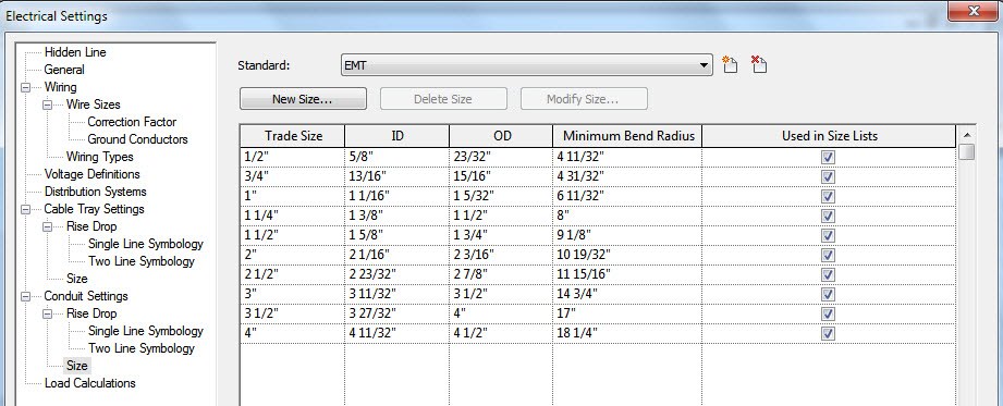
It comes out of the box with various sizes that include inside and outside diameters. You also have control of customizing various cable tray and conduit sizes as well.
You can control the Detail Level and control the Visibility and Graphics of conduit and cable tray to control the display those objects just as you can currently control the display of piping and duct.
You can check for interferences of cable tray and conduit with other types of objects in your project model.
 You can schedule cable tray and conduit using the same procedures that you used to schedule pipe and duct. When you draw cable tray or conduit without using the no-fittings opition, it is scheduled as a single run.
Electrical Demand Factors
You can use demand factors to adjust the rating of the main electrical service for a project. This is used since not all electrical equipment will be on all the time.

There are many demand factors that come out of the box, and you can easily create additional demand factors that are needed for the codes in your area. The demand factor can be determined by a constant value or percentage, or by the quantity of connected objects or by load.
These demand factors are assigned to various load classifications which are then assighed to electrical connectors.
Tagging on Placement
There is a new Tag on Placement option that automatically adds a tag for a component when it's placed in the model. Once the tool is selected, you'll have options in the options bar of it's placement.
Companion Flanges
You can add flanges to your pipes and are separate objects than the pipe itself. So when you make an elbow, there are actually 5 components. Two pieces of pipe, one elbow, and two companion flanges. You must make sure that the flanges are loaded into your project and assigned to your pipe type to be inserted automatically. You can, however add flanges manually as well.
Oval Duct
Finally, Revit now has oval duct to add to it's current round and rectangular duct types. Make sure to load the oval duct fittings into your project and assigned to your oval duct type. You have the same parameteres to size oval duct as you did with round and rectagular duct.

Placing Valves and Fittings in Section or Elevation Views
This is another big one. When you have stacked pipe, and need to put a valve on the bottom pipe, you always had to temperarily hide the upper pipe to place the fitting on the lower pipe. And putting a valve on a vertical pipe was difficult and very time consuming.
New Electrical Content
New content has been created for electrical components. Most of the content is located within the Electrical Compnents folder. The content folder is slightly different than in 2010 so be careful when creating your new 2011 library folder.
Thursday, March 18, 2010
Autodesk Publishes Framework to Help AEC Professionals Implement BIM Process

- BIM support materials for owners, architects, engineers, and contractors
- Templates to streamline multi-discipline communications
- Recommendations for roles and responsibilities
- Best business process examples
- Software suggestions for an effective BIM environment
SAN RAFAEL, Calif - Autodesk, Inc has announced the availability of its Autodesk BIM (Building Information Modeling) Deployment Plan: A Practical Framework for Implementing BIM, a new web-accessible resource for building industry professionals. Aimed at all AEC stake-holders, including owners, architects, engineers and contractors, the free guide includes support materials and a framework based on real-world applications of BIM. Tools offered include templates to help manage multi-discipline communications within a BIM project, as well as suggestions for the roles and responsibilities of each party in a BIM process-based project, best business process examples and suggested software to support an effective BIM environment.
“The BIM Deployment Plan is helping us develop a BIM implementation process best suited for the technology needs of the project and tailored to the abilities of the players involved. It is also helpful in defining clear roles and responsibilities for the execution of workflows on our jobs.”
As the building industry continues to evolve, technologies such as visualization, simulation and analysis are fundamentally changing how projects get delivered. Now more than ever, collaboration and transparency are essential and effective for anticipating and reducing problems related to cost overruns, schedule, scope and quality. Autodesk has been at the forefront of BIM technology adoption including the creation of a portfolio of software products that facilitate a BIM solution.
“New technology is creating enormous opportunities for the building industry to improve processes and outcomes, and many organizations still need guidance on how to share information as well as streamline project communications,” said Phil Bernstein, FAIA, Autodesk vice president of building industry strategy & relations. “The Autodesk BIM Deployment Plan was designed to help companies navigate the entire process via one collaborative framework and subsequently deliver projects faster, more economically and with reduced environmental impact.”
“As strong advocates of BIM, we can develop building design strategies that are extremely well integrated and coordinated, substantially increasing our efficiency and lessening the building time – all of which allow us more time to create inspiring designs for our clients,” said Dick Thomas, vice president at SHP and executive director of 2enCompass. “Now taking this a step farther, The Autodesk BIM Deployment Plan has helped us further advance BIM project implementation by better documenting stakeholder roles and responsibilities and most importantly, helping us deliver the right information from the project model to the right people at the right time to drive our project forward.”
“Communication and collaboration amongst strategic team players is vital to the success of our projects,” said Mark Konchar vice president at Balfour Beatty Construction, Washington division. “The BIM Deployment Plan is helping us develop a BIM implementation process best suited for the technology needs of the project and tailored to the abilities of the players involved. It is also helpful in defining clear roles and responsibilities for the execution of workflows on our jobs.”
Thursday, March 04, 2010
Bell & Gossett products now available in Revit format

Benefits of the Bell &Gossett (www.bellgossett.com) Revit content include: Easy access to integrated content in Autodesk Revit, eliminating the need to search and download files from external websites Fully certified content created by CADworks and approved by Bell & Gossett Bell & Gossett content is created in the latest Revit version (2010), and will be automatically upgraded to future generations, requiring no user patch downloads Changes to designs are automatically updated across the entire project and are easy to track; there is no need to re-enter information Multiple simultaneous design alternatives are allowed within projects Flexibility and control over visualization of projects"This new Building Information Modeling drawing library will be very beneficial for mechanical system designers at architects, engineers, contractors, fabricators, building owners," said Mark Handzel, Director of Building Services, Americas at ITT Residential & Commercial Water. "The on-line design will eliminate the need for downloading extensive libraries of drawings and assure that all drawings are 100% accurate."
Revit Content Setup and Use Video
Wednesday, February 10, 2010
RevitCatalog.com
For Architects
RevitCatalog.com is the online connection between building products manufacturers and the architects who specify them. RevitCatalog.com is built specifically as a companion to the "Family Automation Revit" (FAR) program—a service of CAD Enhancement, Inc.—which allows architects to receive up-to-date Revit Family (RFA) files directly from the manufacturer for use in daily design inside any of Autodesk's Revit family of products.
Top Quality Content
The parts you find at RevitCatalog.com are not like other Revit Family sharing sites. Our parts are not user-generated. Instead, we partner with building product manufacturers to create intelligent, stable, and usable Revit Families. What's more, every part on RevitCatalog.com has been tested and validated by our staff before being published live. Don't jeopardize your entire project for free content. Check RevitCatalog.com first.
The FAR Manager
In order to download and use parts from RevitCatalog.com, you must use the FAR Manager to import our proprietary transfer format into Revit. The .FAR file format is a tiny file, compressing the complex geometric data of a .RFA file for easy transport and storage.
Friday, February 05, 2010
Ruskin HVAC Revit Families Available

Ruskin is pleased to announce the availability of Revit® 3-D files of select products.
A list of models containing Ruskin Revit families are available here! or by visiting the Autodesk Seek website
Revit file solutions providing information for…
•Interdisciplinary Data Sharing
•Project Scope Communication
•Schedule Creation
•Rapid Attribute Modification
•Energy Analysis
A list of models containing Ruskin Revit families are available here! or by visiting the Autodesk Seek website
Revit file solutions providing information for…
•Interdisciplinary Data Sharing
•Project Scope Communication
•Schedule Creation
•Rapid Attribute Modification
•Energy Analysis
Download Various application Files
•Ruskin Dampers
◦Life Safety
◦Air Control
◦Industrial/Process
•Ruskin Louvers
◦Drainable
◦Wind-Driven Rain
◦Hurricane
◦Sun Shades
•Ruskin ERV Units
You may download their full Revit Catalog at the link here. In order to stay up-to-date with any changes and additions to the catalog, they encourage you to sign up for our e-Specifer newsletter by providing your email address
Thursday, February 04, 2010
EUA Launches Design Application Consulting (BIM) Services
EUA Launches Design Application Consulting (BIM) Services

Eppstein Uhen Architects (EUA) has just launched an extension of the firm; Consulting: Design Applications
http://www.eua.com/consulting/da/
Check out their recent marketing blast!
Loren Cook families for Autodesk Revit MEP
 Autodesk Revit families are available for every model and configuration of Loren Cook product. Each 3D parametric family is a full-scale representation of the product and contains all sizes available for that model. Each family includes information on duct connection size, electrical connection location, mounting holes (where applicable) as well as user defined attributes for airflow, static pressure, RPM, horsepower, voltage, phase, etc.
The files designed by Loren Cook are for use in Autodesk Revit MEP 2009 or later. The files are free to download and are intended to be inserted using the standard Mechanical Equipment placement commands. Each family will need to be loaded into the user's project proir to use.
Click here to access their library of Revit files.
Friday, January 29, 2010
New Version of Trimble MEP Field Software Enables Faster, Easier and More Accurate Layout of Conduit, Pipe, Duct and Cable Trays
Trimble MEP 2.0 Field Software Introduces Significant New Features to Benefit Mechanical, Electrical, and Plumbing Contractors Working in Building Construction Applications
ORLANDO, Fla. -- Trimble introduced today a new version of Trimble® MEP Field Software for Mechanical, Electrical and Plumbing (MEP) contractors. Trimble MEP 2.0 is the world's first layout solution designed specifically to allow contractors to take digital CAD design file or 3D Building Information Model (BIM) into the field to simplify the layout of conduit, pipe, duct and cable trays. The new version of Trimble MEP Field software can increase the contractor's productivity by reducing rework by facilitating faster, easier and more accurate layout.
The announcement was made today at the AHR Expo 2010, the world's largest show targeting air conditioning, heating and refrigeration contractors.
The Trimble MEP 2.0 field software introduces new, industry-unique functionality to further assist mechanical, electrical and plumbing contractors in bringing rich digital design data directly from the office to the job site. Version 2.0 affirms Trimble's commitment to creating a seamless and more efficient solution for customers. Significant new features in Trimble MEP 2.0 include:
-- The ability for users to create points directly from a DXF file into Trimble MEP running on the Trimble Nomad® Controller. Previously, points had to be created on a PC or via other methods. This critical new function enables mechanical, electrical and plumbing contractors to respond to situations on the job as they arise without having to return to the office, which can provide significant time savings and increased efficiency.
-- The Direct Reflex (DR) Layout feature makes locating points on a deck or overhead fast and efficient because users do not need to know elevation in order to achieve an accurate location--Trimble MEP determines the elevation automatically and turns the total station to the correct position. Enhanced DR Layout in version 2.0 extends this capability to walls: regardless of the orientation or design of a wall, Trimble MEP 2.0 will calculate the correct location for piping, duct and other wall penetrations. By eliminating the need for manual calculations and multiple instrument setups, Trimble MEP 2.0 can deliver greater efficiency. In addition, the DR range of the total stations has been significantly increased, allowing contractors to reach further on the jobsite.
These and additional new features in Trimble MEP 2.0 Field Software are designed to meet the needs of mechanical, electrical and plumbing contractors, to deliver streamlined data flow from field to office.
Trimble MEP Field Software version 2.0 is available now through select dealers in Trimble's North American Building Construction distribution network.
About Trimble's Building Construction Business
Trimble's Building Construction Division is a leading innovator of productivity solutions for the building construction contractor. Trimble's solutions target site prep, general, concrete, mechanical, electrical and plumbing contractors on large and small commercial, industrial and residential jobsites. Trimble is focused on delivering solutions that tightly link office based process and information with the field crew--including taking Building Information Models (BIM) and other design data to the field for highly accurate positioning and layout of foundations and mechanical, electrical and plumbing systems. Trimble solutions provide a high-level of process and workflow integration from the design phase through to the finished project--delivering significant improvements in productivity throughout the building construction lifecycle.
About Trimble
Trimble applies technology to make field and mobile workers in businesses and government significantly more productive. Solutions are focused on applications requiring position or location--including surveying, construction, agriculture, fleet and asset management, public safety and mapping. In addition to utilizing positioning technologies, such as GPS, lasers and optics, Trimble solutions may include software content specific to the needs of the user. Wireless technologies are utilized to deliver the solution to the user and to ensure a tight coupling of the field and the back office. Founded in 1978, Trimble is headquartered in Sunnyvale, Calif.
For more information Trimble's Web site at www.trimble.com.
CONTACT: Willa McManmon, Investors, +1-408-481-7838, willa_mcmanmon@trimble.com, or Lea Ann McNabb, Media, +1-408-481-7808, leaann_mcnabb@trimble.com; both of Trimble
Saturday, January 16, 2010
Download the Revit Model Style Guide V2.1
From Autodesk's Seek Manufacturers website, you can find the latest Revit Model Style Guide.
Autodesk has put out another revised version of the Model Style Guide. The purpose of this guide is to define Autodesk guidelines and standards for model content creation in Revit Architecture, Revit MEP, and Revit Structure. Model content refers to the two‐dimensional and three‐dimensional standard component families that are used to create elements that represent manufactured content (for example, windows, furnaces, heat pumps, and structural steel members).
By following the guidelines and standards in this guide, content creators will ensure the portability and performance of their content, and fulfill the necessary distribution requirements for the Autodesk Seek web service. The Autodesk Seek web service requires:
- the uniform display of products offered by a single manufacturer
- complete, consistent, and accurate presentation of product data across manufacturers
- the full use of Autodesk Seek search capabilities
Go with the leaders. Working with industry experts and standards organizations, Autodesk has developed the Revit Model Style Guide to help you develop consistent, useful Revit models that design professionals can use with confidence.
Revit Model Style Guide
(zip - 3910Kb)
Subscribe to:
Posts (Atom)