Revit MEP

Revit MEP

Tuesday, April 29, 2008

New Rendering Engine in Revit 2009 Platform

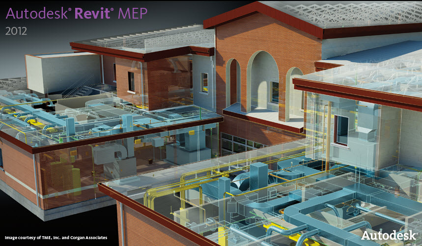
Rendering in Revit with mental ray makes it possible to render photorealistic exterior and interior scenes.

Photometric lights and mental ray materials allow views to be rendered inside of Revit. Environment settings and entourage add life to the rendered scenes.


The first image was a precanned view but I added some light fixtures, and rendered the scene to be a night scene and adjusted some settings to show off the lighting.

The second image was already completed by Autodesk, and I just exported it out of the project. But these are just objects in Revit that have materials assigned to them, and light fixtures that have ies photometrics and light sources attached to them.

There isn't much for setting up of lights in the rendering proceedure. Other than the ability to turn some lights on and some lights off in light groups and you can also dim the light groups in Revit rendering. The lights will render as what they are in the family. Last is the Light Source Definition that is new in 2009. You can choose the shape and distribution that the light gives off. This and the IES photometric file can be used for both point-by-point analysis in 3rd party programs and for renderings in Revit MEP.

Sunday, April 20, 2008

Now Released - Revit MEP 2009

Content is very important to our business. In addition to the new content of last years content extension, which more than doubled the MEP components available for use in Revit MEP, a significant amount of new content has been added to the 2009 version:

  • Commercial condensing units up to 130 tons
  • Air-cooled and water-cooled vertical packaged systems up to 60 tons
  • Horizontal and vertical belt-drive DX and CW fan coils, stacked fan coils, and ceiling-mounted fan coils
  • Packaged air handlers up to 25 tons
  • Gas-fired and electric commercial packaged rooftop units to 130 tons
  • Down-flow, vertical, and horizontal high-efficiency water source heat pumps up to 20 tons
  • Occupancy and daylighting sensors
  • Consolidation of Revit Architecture light catalogs with Revit MEP catalogs
  • Volumetric and direct-indirect lights.

You can support sustainable design efforts using Revit MEP 2009 by using built-in duct, pipe, and electrical sizing tools dynamically interact with the BIM and built-in heating and cooling load analysis tools to optimize system design for maximum efficiency and more accurately predict the performance of building systems. Export to gbXML (green building extensible markup language) and API (application programming interface) links allow industry-standard tools such as Integrated Environmental Solutions’ (IES ) to further optimize building designs for energy analysis, lifecycle cost, CFD, daylight, solar gain studies, and many other types of building performance analysis.


Sustainable design tools in AutoCAD Revit MEP Suite include:

  • Duct sizing
  • Pipe sizing
  • Plumbing fixture unit sizing
  • Electrical feeder sizing
  • Panel schedule loads
  • Heating/cooling loads
  • Solar shading
  • gbXML export to trace 700, IES , and others
  • API link to IES

System Recommendations

  • Intel Core™ 2 Duo, 2.4 GHz or equivalent AMD Athlon processor
  • Windows XP Professional SP2 or later
  • 4 GB RAM
  • 4 GB disk space
  • Dedicated video card with hardware support for OpenGL spec 1.3 or later

Click Here to Download The Detailed Brochure

Revit MEP can be run immediately after downloading and installation in a fully functioning trial mode for 30 days. Upon first use of Revit MEP, a licensing wizard will be displayed. Select 'Run the product'. To later register the product, choose "Product and License Information" from the Help menu and follow the registration instructions in the following sections.

Click Here To Download Revit MEP 2009 Program

After Trial mode has expired, Revit MEP may still be used in Demo mode. In Demo mode you can open existing Revit files, view and print them and explore Revit MEP and all its functionalities prior to any purchase. However, if you create a model in demo mode or change an existing model, you will not be able to save or print those changes. In order to use Revit MEP in Demo mode select the Demo/Viewer radio button in "Product and License Information" dialog accessible from the Help menu.

Friday, April 04, 2008

BIM to take LEED to the next level

Read the Article at Contract Magazine

Imagine a highly sophisticated building integrated modeling (BIM) software capable of calculating real-time energy and water use levels, for example, and USGBC LEED points based upon evolving design decisions, as they're made. This "dashboard concept" is the centerpiece of a one-year-old joint partnership between the USGBC and Autodesk, which was presented as a vision of the future at Greenbuild in 2007. Essentially, Autodesk's Phil Bernstein, FAIA, LEED AP, vice president of AEC industry strategy and relations, explains the concept as a "platform that allows you to predict the behavior of your building before you construct it, via a convergence of modeling, analysis, and sustainable validation into an improved design process."
With the USGBC planning to revamp LEED into a more intelligent system, more capable of assessing the environmental impact of the built environment, BIM stands to better enable this goal. "From a strategy perspective, the USGBC recognizes that part of the green building movement is going to have to be technology-driven," acknowledges Max Zahniser, LEED AP, NCARB, formerly LEED's program manager for process and integration, and currently principal of Praxis-Building Solutions, Philadelphia.
Zahniser, who has remained the USGBC's representative in the Autodesk partnership despite becoming an independent consultant, further explains. "There is just a small set of green building gurus capable of assessing their design decisions as they are made. We wanted to make it possible for more than just the gurus to be able to design successful green buildings." Now that the "conceptual stake has been placed in the ground," the USGBC and Autodesk are rolling up their sleeves to develop this software with the hope of creating a more integrated design process via a holistic approach to building systems.
For example, if the design team knows how sophisticated its daylighting system is, thanks to data generated by the next-generation software, the decision can more accurately be made to utilize fewer fixtures. Similarly, the team can track the trade-off between LEED daylighting and energy credits by experimenting with different shading devices and glazing systems on the building model. Or by tracking the efficiency of the building envelope, the HVAC system can then be accurately downsized and the baseboard heating system eliminated. "Such a building tool will allow the user to quickly understand the complete interdependence between different systems and the environment," claims Bernstein.
When Autodesk originally got involved with the USGBC through the decision to help sponsor Greenbuild a couple years back, the two organizations discovered that they possessed a similar vision of buildings and the environment. "Seeing the world in really similar ways, with lots of synergies, we all hit it off really well," Bernstein reflects.
Thus, the decision was made to enter into a strategic partnership, officially announced at Greenbuild 2006. In addition to the technology aspect of the relationship—to which USGBC brings functionality required by the end-user to the table, while Autodesk provides the technical expertise—are two additional components: education and consulting. So far, the two groups have teamed up to create a sustainable design curriculum for schools of architecture, and Autodesk has been called upon as a consultant to offer technical advise to USGBC on a couple of other projects.
Although USGBC and Autodesk's different teams have been predominately working together on an informal level, Bernstein describes the relationship as potent, having achieved quite a bit in just one year of collaboration.

Thursday, April 03, 2008

Revit MEP Coordination Views

When you are using either a Mechanical or Electrical view disipline, the view will display those objects darker than the architectural objects or other MEP objects. You can see from this Mechanical 3D view below, the walls are light, and you can see the piping going through it.


If you change the view properties so it is displaying using a coordination disipline instead, the walls will become darker, and the piping will be hidden behind the wall objects. But it will not display the piping with hidden lines.


If you create plan views using Coordination disipline, you can see the pipe that goes through the wall or under a light fixture or another pipe as disappearing.


When in plan mode, and the view set to a mechanical disipline, you can see those pipes passing below other MEP objects as hidden lines, but not shown hidden through the wall objects as shown below.


To do this, you'd probably need to use a basic line tool for this. Perhaps there will be more control provided for this feature in the future. For now the above workaround may help.