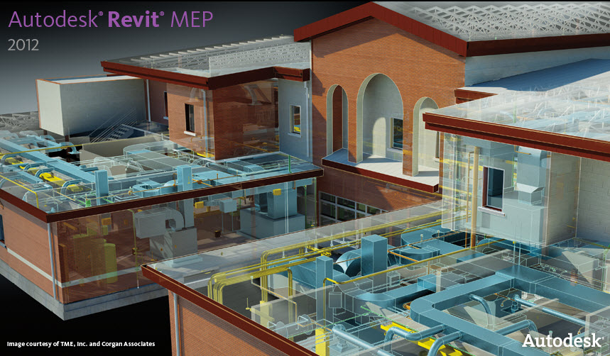
Collaborating in an all-Revit environment will greatly improve the coordination of building components through its internal management of the project database. This tutorial provides some guidelines on how to undertake effective multi-disciplinary collaboration in Revit.
Collaboration Guidelines
Revit consists of three discipline-specific platforms: Revit Architecture, Revit Structure, and Revit MEP. Each team member must be working on the same platform version and product build to effectively collaborate. Revit is a forward compatible product. Therefore, the design team should know the current compatible platform versions.
The current compatible Revit platform versions are recommended below:
- Building 8, Structure 1 (MEP application was not developed at this time)
- Building 8.1, Structure 2 (MEP application was not developed at this time)
- Building 9, Structure 3, Systems 1
- Building 9.1, Structure 4, Systems 2
- Architecture 2008, Structure 2008, MEP 2008
It is recommended that product build numbers should match in each product. The product build can be located in each product's Help menu by clicking on About Revit… The same build should be issued to all team members in the same firm or errors could occur when trying to Save to Central when using Worksharing.

Collaborations Tools and Methods
The linking of each other's models using Revit's Copy/Monitor feature provides immediate visual feedback on what the other members are doing. The benefits include:
- The ability to see the each other's data in full context of the project
- The ability to graphically control the linked data to enhance how it is viewed.
- Support for Coordination Monitor and Interference Check.
The Coordination Monitor is the most intelligent tool for collaborating in Revit when utilized properly. The benefits include:
- The ability to choose components of the linked model to monitor for change.
- Multiple modes offer flexibility to Monitor and Copy/Monitor objects.
- With Copy/Monitor, elements from the linked model can be copied into the host project automatically creating a monitored relationship.
The Interference Check provides immediate feedback on component collisions. The benefits include:
- The ability to check interferences within a single project or linked models.
- The ability to check "On Demand."
Project Structure
Effective collaboration can be achieved in a single model environment. However, it is recommended that the models be separated from one another to gain full advantage of the collaboration tools provided in Revit.
Workflow Relationships
Each discipline creates a relationship based on their individual workflows:
- Architect/Structural Engineer: In this relationship, the structural engineer will leverage the architect's model using Coordination Monitor's Copy/Monitor mode to create copies of building components from the architect's model and to monitor it for change, as well as to establish a quick structural model of the project for their workflow. The architect can then use Interference Check to verify that architectural elements are not conflicting with structural components.
- Architect/MEP Engineer: In this relationship, the MEP engineer will link the architect's model to position components in context. The Coordination Monitor is used to leverage the architect's rooms and levels. Analysis parameters are added to the room elements. However, levels are necessary to copy/monitor rooms. The architect simply links the MEP model to show system elements in context to architectural elements.
- Structural Engineer/MEP Engineer: In this relationship, both parties benefit from interference detection to avoid collisions between structural and systems elements.
Based on these recommendations, the diagram below represents a suggested use of Revit's collaboration tools between each program/discipline.
- The Architect will link in the Structural model and utilize Interference Check.
- The Structural Engineer will link in the Architectural model and utilize Coordination Monitor.
- The Architect will link in the MEP model and utilize Linked Models.
- The MEP Engineer will link in the Architectural model and utilize Coordination Monitor.
- The Structural Engineer will link in the MEP model and utilize Interference Check.
- The MEP Engineer will link in the Structural model and utilize Interference Check.

Here are some overall guidelines on workflow procedures to keep in mind:
- Use the Coordination Monitor only when necessary. Overuse of the Coordination Monitor could slow the linked model's performance. Some relationships need only be set up as a monitor, not a copy/monitor.
- When Worksharing is invoked, be sure to follow these recommendations:
- Coordination Monitor should be set up to Central File if both files exist on the same LAN. All updates should occur when the Local Files are not being used.
- Open the project and Detach from the Central File when distributing the model to other consultants. The detached model should then be attached to the consultant's Central File.
Stage 1 - Leveraging Models
Architect to Structural Engineer
1. The Architect will send the architectural model to the Structural Engineer.
2. The Structural Engineer opens the delivered model and reviews its elements.
- Levels: Do they make sense for use in the structural model? Do the bubbles vary from the company standard?
- Grids: Do the bubbles vary from the company standard?
- Columns: What type of columns are available? Are the columns continuous or split?
- Walls: Are there structural walls needed in this project? What kind of walls were used?
- Floors: What kind of floors were used?
3. The Structural Engineer starts a new project.
4. The architectural model is linked in. This is accomplished by File > Import/Link > Revit. Use the Origin to Origin positioning method if shared coordinates are not being utilized.

5. The visibility settings are changed to view the architectural model.
6. The Structural Engineer selects Tools > Copy/Monitor > Select Link and then selects the architectural model.
7. The Design Bar changes to reveal the Copy/Monitor tools.
8. The Options button is accessed to reveal the Copy/Monitor settings for Levels, Grids, Columns, Walls, and Floors.

9. The Structural Engineer monitors or copy/monitors the elements of the architectural model that are required to begin the structural model.
10. The structural model will continue being developed.
Architect to MEP Engineer
1. The Architect will send the architectural model to the MEP Engineer.
2. The MEP Engineer opens the delivered model and reviews its elements.
- Levels: Are necessary for copy/monitor of rooms in the MEP model? Do the bubbles vary from the company standard?
- Grids: Not really necessary.
- Columns: Not really necessary.
- Walls: Not really necessary.
- Floors: Not really necessary.
- Rooms: Are there rooms available?
3. The MEP Engineer starts a new project.
4. The architectural model is linked in. This is accomplished by File > Import/Link > Revit. Use the Origin to Origin positioning method if shared coordinates are not being utilized.
5. The visibility settings are changed to view the architectural model.
6. The MEP Engineer selects Tools > Copy/Monitor > Select Link and then selects the architectural model.
7. The Design Bar changes to reveal the Copy/Monitor tools.
8. The Options button is accessed to reveal the Copy/Monitor settings for Levels, Grids, Columns, Walls, Floors, and Rooms.

9. The MEP Engineer monitors or copy/monitors the levels first.
10. The Options tool will be accessed again to review and set the room options.
11. Several of the room's parameters can be copied from the architectural model.

12. The rooms can be copied by phase if necessary.

13. After setting these options, the rooms can be copied using the Copy Rooms tool on the Design Bar.
14. The MEP model will continue being developed.
Stage 2 - Monitoring Models
Structural Engineer to Architect
1. The Structural Engineer will send the structural model to the Architect.
2. The structural model is linked in. This is accomplished by File > Import/Link > Revit. Use the Origin to Origin positioning method if shared coordinates are not being utilized.
3. The Architect can run Interference Check at this point but might elect to monitor the levels and grids to access additional features of Coordination Monitor.
Stage 3 - Coordinating Changes
The Architect
1. If the architectural model changes, this will initiate a warning dialog from Revit.

2. The changes can be viewed by accessing Tools > Coordination Review > Select Link.
3. Coordination Review will open revealing the alert. As the host, the Architect can post a comment regarding this coordination issue.

4. The architectural model is saved and sent to the consulting engineers.
The Structural Engineer
1. The Structural Engineer will receive the new updated architectural model.
2. It should be saved in the location of the previous version.
3. The structural model will then be opened.
4. Revit will immediately alert the user of a Coordination Monitor issue.

5. The Structural Engineer will access Tools > Coordination Review > Select Link.
6. Coordination Review will open revealing the changes.
7. On the In a linked project tab, the Structural Engineer can review any comments made by the architect.

8. On the In host project tab, the Structural Engineer can initiate an action.
- Postpone / Do Nothing: Leaves the change to be addressed at a later time.
- Reject: There is a difference in the host file and its associated monitored element. The change made to the element in the host file is incorrect and the associated monitored element needs to be changed.
- Accept Difference: Accepts the change made to the element and updates the new relationship.
- Modify, Rename, Move: The command name changes based on the action. The change is propagated to the host project clearing the queue.
Stage 4 - Interference Checking
The Structural Engineer to the MEP Engineer
1. The MEP Engineer will receive the new updated structural model.
2. It should be saved in the location of the previous version.
3. The MEP model will then be opened.
4. The MEP Engineer will access Tools > Interference Check > Run Check.
5. In the Interference Check dialog, the user can choose objects from the current project and compare them to that of a linked project.

6. The Interference Report dialog will display all instances of conflict.

7. These items can be revealed in any available views by Revit. One by one, they can be addressed.
8. The report can be refreshed to see if the conflicts were resolved through Tools > Interference Check > Show Last Report.
9. The goal is the message below.

This process continues over and over. Each discipline can function as a united team to deliver the full conflict-free building information model.