Revit MEP

Revit MEP

Monday, August 16, 2010

NIBCO and CADworks Partner to Deliver High-Quality BIM Content to AEC Firms


From: http://pr-usa.net/index.php?option=com_content&task=view&id=460131&Itemid=33

NIBCO and CADworks Partner to Deliver High-Quality BIM Content to AEC Firms


NIBCO and CADworks, a leading Autodesk® Revit® content-solutions provider, have collaborated to provide NIBCO® specified valves to the architectural, engineering and construction (AEC) community through the Autodesk® Seek Library (http://seek.autodesk.com) (type 'NIBCO' in the search bar for full product listing).
"NIBCO takes an active role in staying abreast of emerging trends and technology," said NIBCO's Chairman and CEO Rex Martin. "Our alliance with CADworks allows design professionals to easily download and integrate data-rich 3D models of NIBCO specified valves directly into their digital building information models (BIM)."
As a part of its BIM initiative, NIBCO's family of bronze ball valves and ductile iron butterfly valves are now available for download from the Autodesk® Seek Library. The remainder of NIBCO® specified valves will be made available over the next six to 12 months.

CADworks' expertise in content creation will enable users to download NIBCO® products as 3D models, 2D drawings, and critical product and data specifications from Autodesk® Seek so that Revit® users can design an accurate BIM model.

Tuesday, July 13, 2010

Dependent Views, Matchlines, and View References in Revit: by Reid Addis

Dependent Views, Matchlines, and View References in Revit

Author: Reid Addis, Microsol Resources
Date Published: March 24, 2009

Autodesk University Article Link

Dependent Views were added to Revit in Release 2008. The concept behind Dependent Views is to allow you to maintain consistent annotation and View Scale among the main and dependent views while permitting independent crop regions for each view. A secondary result is that Dependent Views allow you to place different cropped portions of the overall View on different sheets while maintaining consistency of annotation and scale across sheets.

Normally when you simply Duplicate a view with Detailing, all of the annotation (text, dimensions, tags, etc.) become independent from the original view along with the View Scale. Thus if you change the value of the original object (adjust a dimension or edit text or delete a Room Tag) in one view, it has no effect on the duplicated object in the independent duplicated view.

This is not the case with Dependent Views. The annotation and view scale are identical across all the views. Change the view scale in ANY dependent or parent view, and it changes the view scale in ALL the dependent and parent views. In addition, the annotation is identical as well, so a change in ANY view again affects that same object in ALL views.

Using the “Getting Started” tutorial that comes with Revit Architecture 2009, I’ve created some Dependent Views of the Lower Level:

View 1


For clarity, I’ve turned on the Crop Region in the Parent View and added some Filled Regions to show the Dependent View Crop Regions. The “purple” area in the center indicates where these two regions overlap. This is where we will add a Matchline and View References in the Parent View to help coordinate locating these adjacent views when placed on different sheets.

Below are the two Dependent Views with the Matchline displayed that was added in the Parent view from the Drafting rollout of the Design Bar:


View 2

In the Parent View, from the Drafting rollout on the Design Bar, I will place a View Reference on each side of the Matchline.


View 3


Notice that as you place the View Reference, the Option Bar gives you the ability to specify which Dependent View is being referenced. Thus the View Reference placed in the West view will target the East view, and visa versa.

Equally critical is making sure that you actually have a Tag loaded from the View Reference Family. By default, this is set to and thus will fail to work.

View 4

The final step is to place these Dependent Views on Sheets, then watch how the View References update to include this information.


View 5

Notice that the View References now show which View and Sheet number the Matchline adjacent view is on.


View 6


I hope this clears up any confusion you may have had about Dependent Views, Matchlines, and View References.

Wednesday, June 23, 2010

Revit File Library | Viking - Fire Sprinklers, Valves, and Systems


Revit® File Library Viking - Fire Sprinklers, Valves, and Systems

Below is a list of all Revit files currently available for Viking valves and systems. More files will be added in the future, so be sure to check back soon.


Check Valves
1. Model J-1 Alarm Check Valve
2. Model E-1 Easy Riser Check Valve
3. Model F-1 Easy Riser Check Valve
4. Model K-1 and Model L-1 Check Valves
5. Model M-2 Check Valve


Check Valve Trim
6. Model J-1 Alarm Check Valve Vertical Trim
7. Model E-1 Easy Riser Check Valve Trim
8. Model F-1 Easy Riser Check Valve Trim
9. Model K-1 and L-1 Easy Riser Check Valve Trim


Deluge Valves
10. 2" Model E-1 Deluge Valve (Angle Style)
11. 3", 4", and 6" Model E-1 Deluge Valve (Angle Style)
12. 2"-6" Model E-2 (Halar Coated) Deluge Valve (Angle Style)
13. Model E-3 Deluge Valve (Angle Style)
14. Model E-4 Deluge Valve (Angle Style)
15. 1-1/2" and 2" Model F-1 Deluge Valve (Straight Through)
16. 1-1/2" and 2" Model F-2 (Halar Coated) Deluge Valve (Straight Through)
17. 2-1/2"-8" Model F-1 Deluge Valve (Straight Through)
18. 2-1/2"-8" Model F-2 (Halar Coated) Deluge Valve (Straight Through)


Deluge Valve Trim
19. 2" Model E-1 Deluge Valve Trim (Angle Style)
20. 3", 4", and 6" Model E-1 Deluge Valve Trim (Angle Style)
21. 3", 4", and 6" Model E-1 (Stainless Steel) Deluge Valve Trim (Angle Style)
22. Model E-3 Deluge Valve Trim (Angle Style)
23. 1-1/2" and 2" Model F-1 Deluge Valve Vertical Trim (Straight Through)
24. 1-1/2" and 2" Model F-1 Deluge Valve (Stainless Steel) Vertical Trim (Straight Through)
25. 2-1/2" and 3" Model F-1 Deluge Valve Vertical Trim (Straight Through)
26. 2-1/2" and 3" Model F-1 Deluge Valve (Stainless Steel) Vertical Trim (Straight Through)
27. 4" Model F-1 Deluge Valve Vertical Trim (Straight Through)
28. 4" Model F-1 Deluge Valve (Stainless Steel) Vertical Trim (Straight Through)
29. 6" Model F-1 Deluge Valve Vertical Trim (Straight Through)
30. 6" Model F-1 Deluge Valve (Stainless Steel) Vertical Trim (Straight Through)
31. 8" Model F-1 Deluge Valve Vertical Trim (Straight Through)
32. 8" Model F-1 Deluge Valve (Stainless Steel) Vertical Trim (Straight Through)


Deluge Release Trim
33. Electric Release Trim
34. Pneumatic Release Trim
35. Model H-1 Pneumatic Actuator
36. Solenoid Valve


Preaction Release Trim
37. Electric Release Trim
38. Pneumatic Release Trim


Flow Control Valves
39. 2" Model H-1 Flow Control Valve (Angle Style)
40. 3", 4", and 6" Model H-1 Flow Control Valve (Angle Style)
41. 2", 3", 4", and 6" Model H-2 (Halar Coated) Flow Control Valve (Angle Style)
42. Model H-3 Flow Control Valve (Angle Style)
43. Model H-4 (Halar Coated) Flow Control Valve (Angle Style)
44. 1-1/2" and 2" Model J-1 Flow Control Valve (Straight Through)
45. 1-1/2" and 2" Model J-2 (Halar Coated) Flow Control Valve (Straight Through)
46. 2-1/2"-8" Model J-1 Flow Control Valve (Straight Through)
47. 2-1/2"-8" Model J-2 (Halar Coated) Flow Control Valve (Straight Through)


Dry Valve and Trim
48. Model F-1 Dry Valve
49. Model F-1 Dry Valve and Trim


Model G-4000 Dry Valve
50. Model G-4000 Dry Valve
51. Model G-4000 Drain Manifold

Viking Riser Manifolds
52. Commercial Riser Assemblies
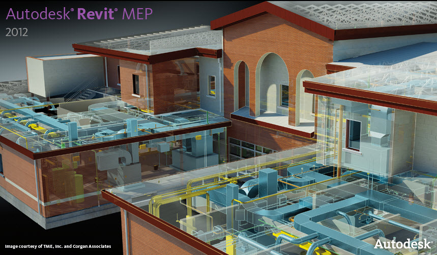
Autodesk® Revit® MEP 2011 Update 1


Download is the latest update for Autodesk® Revit® MEP 2011 software as part of AutoCAD® Revit® MEP Suite 2011 software.  There are separate downloads for the 64 bit and 32 bit versions.

Update 1 is not a full install; rather it is using service pack technology similar to AutoCAD®- based products. Prior to installing the Update 1, please verify that you have already installed the First Customer Ship build of Autodesk Revit MEP 2011.  This is how Autodesk has been pushing updates out lately, which is different than in years past where you had to download and install a whole new build of the program. 

The service pack can be applied to both the standalone and suite versions of Autodesk Revit MEP 2011.  This is also different than in years past.  Autodesk used to have different downloads for the Revit MEP build and the Revit MEP Suite build.

For a list of improvements, please download the Autodesk® Revit® MEP 2011 Update Enhancement List: or see them below.


Update Enhancement List


Improvements made in Update 1 build (20100614_2115):

Autodesk® Revit® MEP 2011 Enhancements

  • Improves stability of the Location dialog.
  • Improves performance of panel schedule views.
  • Allows Calculated Values to be added to Load Summary section in panel schedule templates.
  • Improves display of panel schedule borders.
  • Improves the stability of distribution systems that use a L-G Voltage value of None.
  • Enables Slope and Justification editors for layouts that include duct and pipe accessories.
  • Enables Copy/Move/Array tools for layouts with sloped and non-sloped pipes.
  • Improves sizing when a round takeoff is connected to a rectangular duct.
  • Improves stability when changing the location setting for heating and cooling load calculation in worksharing.
  • Improves stability when connecting conduit to equipment surface.
  • Improves surface connection between different design options.
  • Improves cable tray bend radius control.
  • Improves temp dimension witness line snapping in surface connection edit mode.
  • Improves converting cable tray tee to cross.
  • Improves stability when drawing a cable tray from equipment.
  • Improves stability when editing type properties of electrical equipment.
  • Disables the Modeless Properties Dialog when a value is changed in the Type Selector to avoid confusion or an incorrect property change.
  • Updates the pressure drop calculations through a transition using the coefficient loss method when reporting the static pressure on systems.
  • Improves Move functionality to allow the user to select different views without having to reselect elements.
  • Improves Move and Copy functionality to allow the user to move/copy at any angle when an elbow fitting is included in the selected elements.
  • Improves Move and Copy functionality during movement in 3D views.
  • Improves Move and Copy functionality to maintain depth when used in elevation or section views.
  • Improves Rotation functionality to allow the rotation of sprinklers in elevation views.
  • Disables disconnect warnings when drawing round duct from a rectangular duct using the tap fitting “Tap-Perpendicular”.
  • Ensures the direction of the connector on Air Terminals is verified for the proper orientation of the Air Terminal.
Autodesk® Revit® Platform 2011 Enhancements
  • The list of supported video cards and drivers has been updated.
  • Improves stability in working with families.
  • Improves stability when deleting views.
  • Improves stability when export to gbXML.
  • Improves stability when view "Analytical Surfaces" in the Export gbXML dialog.
  • Correct export of embedded curtain walls to gbXML.
  • Improves stability when export to DWG.
  • Improves stability when export a split view with shared coordinates to DWG.
  • Respects crop region with blocks when exported to DWG in wireframe visual style.
  • Correct placement of annotation when exported to DWG.
  • Improves stability when Export to DWF.
  • Improves stability and performance when working in the Materials dialog.
  • Improves IFC import to display a warning when encountering a geometry issue that would have previously caused instability in some cases.
  • Improves Properties Palette and canvas interaction that caused unstable graphics if family regenerations were interrupted.
  • Updates to placed instances will now occur when reloading a Family Parameter into project environment as a Reporting Parameter.
  • Improves In Canvas Parameter Labeling to allow a Reporting Parameter to be created when an Instance or Type Parameter could not be.
  • Disables Reporting Parameters between In Place Families and Reference geometry.
  • Correct parameter names display within the Decal Dialog.
  • Improves consistency between Revit and Max when exporting lights with IES files via FBX.
  • Restored custom quality setting that controls number of refractions in a rendering.
  • Improves the performance when adjusting the exposure of a rendered image.
  • Improves issues encountered when rendering elements with different phase settings.
  • Repairs upgrade issue with certain light fixtures using IES files.
  • Repairs printing issue where Scope Boxes from Linked files were visible despite Print settings turning them off.
  • Ensures correct orientation of Elevation tags when tag family is edited.
  • Improves stability when switching among the tabs in RVT Links Display Settings.
  • Improves stability when ungrouping arrayed elements.
  • Improves Filter Rules.
Autodesk® Revit® 2011 API Enhancements

  • Elements will now be properly joined when the ExternalCommand concludes when using automatic regeneration and automatic transaction
  • ExportImage(ImageExportOptions ) no longer throws an exception when given a set of views
  • ElementParameterFilters now operate properly against ElementType elements
  • Improves stability when saving a family and there are event subscribers for Save or Save As.
  • Closes the Family editor environment after loading a family via the API
  • Improves stability when using selection APIs to pick grid elements.
  • Dynamic Model Update: GetChangeTypeGeometry() now triggers properly when active type is changed
  • Improves stability for Dynamic Model Update: when registering updaters and more than one application is registered

Tuesday, June 22, 2010

Revit MEP Alternatives to AutoCAD Procedures

Todd Shackelford just got an article published on Autodesk University's Tech Talk site. Check his article out by clicking the link in this sentence. 

It is safe to say that most MEP engineers who are trying to make the switch to Autodesk© Revit© MEP have arrived there by way of a DWG-based product. With years of refined processes in place, it can be difficult for established firms to find solid footing in unfamiliar software that seems to play by completely different rules. Finding ways to incorporate time-tested methods from the AutoCAD© days and improving them for use in Revit MEP can help make the difference between success and failure. The following example shows how Revit MEP can improve upon a layering trick that is used often in AutoCAD.